QR-25 Series
Quincy Compressor
52201-107, December 2012
34
3501 Wismann Lane, Quincy IL - 62305-3116
SECTION 7
REFERENCE INFORMATION
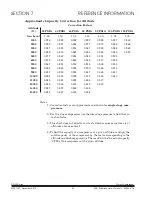
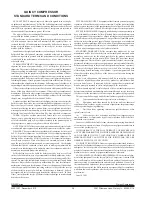
Approximate Capacity Correction for Altitude
Correction Factors
Altitude
(ft.)
25 PSIG 40 PSIG 60 PSIG 80 PSIG 90 PSIG 100 PSIG 125 PSIG
Sea Level
1.00
1.00
1.00
1.00
1.00
1.00
1.00
1000
0.996
0.993
0.992
0.992
0.998
0.987
0.982
2000
0.992
0.987
0.984
0.977
0.972
0.969
0.962
3000
0.987
0.981
0.974
0.967
0.959
0.954
0.942
4000
0.982
0.974
0.963
0.953
0.944
0.940
0.923
5000
0.977
0.967
0.953
0.940
0.931
0.925
6000
0.972
0.961
0.945
0.928
0.917
0.908
7000
0.967
0.953
0.936
0.915
0.902
0.890
8000
0.962
0.945
0.925
0.900
0.886
0.873
9000
0.957
0.938
0.915
0.887
0.868
0.857
10000
0.951
0.931
0.902
0.872
0.853
0.840
11000
0.945
0.923
0.891
0.858
0.837
12000
0.938
0.914
0.878
0.839
0.818
14000
0.927
0.897
0.852
0.805
15000
0.918
0.887
0.836
0.784
Notes:
1.) Correction factors are approximate and shown for single stage com-
pressors.
2.) For two stage compressors use the interstage pressure to find the cor
rection factor.
3.) This chart does not allow for air tools which require more free air at
altitudes above sea level.
4.) To find the capacity of a compressor at a given altitude, multiply the
rated capacity of the compressor by the factor corresponding to the
altitude and discharge pressure. The result will be the actual capacity
(CFM) of the compressor at the given altitude.
Содержание QR-25 210
Страница 42: ......

