background image

1.3

Safety precautions during installation

Precautions during installation

1. The dryer must only be lifted using suitable equipment and in accordance with the applicable safety

regulations. Loose or pivoting parts must be securely fastened before lifting. It is strictly forbidden to
dwell or stay in the risk zone under a lifted load. Lifting acceleration and deceleration must be kept within
safe limits. Wear a safety helmet when working in the area of overhead or lifting equipment.

2. Place the dryer where the ambient air is as cool and clean as possible. If necessary, install a suction duct.

Never obstruct the air inlet. Care must be taken to minimize the entry of moisture at the inlet air.

3. Any blanking flanges, plugs, caps or desiccant bags must be removed before connecting the pipes.
4. Air hoses must be of correct size and suitable for the working pressure. Never use frayed, damaged or

worn hoses. Distribution pipes and connections must be of the correct size and suitable for the working
pressure.

5. The aspirated air must be free of flammable fumes, vapours and particles, e.g. paint solvents, that can lead

to internal fire or explosion.

6. Arrange the air intake so that loose clothing worn by people cannot be sucked in.
7. Ensure that all piping is free to expand under heat and that it is not in contact with or close to flammable

materials.

8. No external force may be exerted on the air outlet valve. The connected pipe must be free of strain.
9. If remote control is installed, the machine must bear a clear sign stating "Danger: This machine is remotely

controlled and may start without warning".
The operator has to make sure that the machine is stopped and that the isolating switch is open and locked
before any maintenance or repair. As a further safeguard, persons switching on remotely controlled
machines shall take adequate precautions to ensure that there is no one checking or working on the
machine. To this end, a suitable notice shall be affixed to the starting equipment.

10. Air-cooled machines must be installed in such a way that an adequate flow of cooling air is available and

that the exhausted cooling air does not recirculate to the inlet.

11. The electrical connections must correspond to the applicable codes. The machines must be earthed and

protected against short circuits by fuses in all phases. A lockable power isolating switch must be installed
near the equipment.

12. On machines with automatic start-stop system or if the automatic restart function after voltage failure is

activated, a sign stating "This machine may start without warning" must be affixed near the instrument
panel.

13. Never remove or tamper with the safety devices, guards or insulation fitted on the machine. Every pressure

vessel or auxiliary installed outside the machine to contain air above atmospheric pressure must be
protected by a pressure-relieving device or devices as required.

14. Piping or other parts with a temperature in excess of 80˚C (176˚F) and which may be accidentally touched

by personnel during normal operation must be guarded or insulated. Other high-temperature piping must
be clearly marked.

15. For water-cooled machines, the cooling water system installed outside the machine has to be protected by

a safety device with set pressure according to the maximum cooling water inlet pressure.

16. If no safety valve is present in the air net close to the desiccant dryer (e.g. safety valve of compressor),

full flow safety valves must be installed on the dryer vessels.

17. If the maximum pressure of the compressor is higher than the design pressure of the dryer, a full flow

safety valve must be installed between the compressor and the dryer in order to blow off the excessive
pressure in case the safety valve of the dryer should be out of order or blocked.

Instruction book

6

2920 7103 90

Содержание QED-250

Страница 1: ...Quincy Refrigerant compressed air dryers QED 300 QED 600 QED 450 QED 250 QED 350 QED 500 Instruction book...

Страница 2: ......

Страница 3: ...or copying of the contents or any part thereof is prohibited This applies in particular to trademarks model denominations part numbers and drawings This instruction book is valid for CE as well as no...

Страница 4: ...CONDENSATE DRAIN SYSTEM 15 3 Controller 17 3 1 INFOLOGIC CONTROLLER 17 3 2 CONTROL PANEL 18 3 3 ICONS AND SYMBOLS USED ON THE DISPLAY 18 3 4 MAIN SCREEN 20 3 5 SCROLLING THROUGH ALL SCREENS 20 3 6 CAL...

Страница 5: ...24 ACTIVATING PASSWORD PROTECTION 34 3 25 SELECTION BETWEEN FLEXIBLE ALARM AND FIXED ALARM 35 3 26 CALLING UP MODIFYING FIXED DEW POINT ALARM SETTING 35 3 27 CALLING UP MODIFYING FLEXIBLE DEW POINT A...

Страница 6: ...ng 53 8 Technical data 57 8 1 SETTINGS OF FUSES 57 8 2 REFERENCE CONDITIONS AND LIMITATIONS 57 8 3 AIR DRYER DATA 58 9 Pressure equipment directives 60 10 Declaration of conformity 61 Instruction book...

Страница 7: ...trained specialized personnel 5 The dryer is not considered capable of producing air of breathing quality To obtain air of breathing quality the compressed air must be adequately purified according to...

Страница 8: ...olled machines shall take adequate precautions to ensure that there is no one checking or working on the machine To this end a suitable notice shall be affixed to the starting equipment 10 Air cooled...

Страница 9: ...g to carry out routine checks Wear ear protectors when removing a panel 7 People staying in environments or rooms where the sound pressure level reaches or exceeds 90 dB A shall wear ear protectors 8...

Страница 10: ...source with open flame for inspecting the interior of a machine pressure vessel etc 14 Make sure that no tools loose parts or rags are left in or on the machine 15 All regulating and safety devices sh...

Страница 11: ...ply to machinery processing or consuming air or inert gas Processing of any other gas requires additional safety precautions typical to the application which are not included herein Some precautions a...

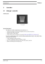
Страница 12: ...point This causes the water to condense The condensate is automatically drained The dried air is warmed up before leaving the dryer An Infologic controller controls and protects the dryer QED 250 up t...

Страница 13: ...600 side view The front panel and the side panel can be removed for service operations Reference Designation 1 Supply cable passage Dm Manual drain valve Da Automatic drain connection Instruction boo...

Страница 14: ...250 up to QED 600 internal view Reference Name 1 Compressor 2 Condenser 3 Heat exchanger 4 Condenser fan 5 Hot gas bypass valve 6 Capillary tube 7 Refrigerant dryer filter Instruction book 12 2920 710...

Страница 15: ...The air then flows through heat exchanger evaporator 2 where the refrigerant evaporates causing the air to be further cooled to close to the evaporating temperature of the refrigerant More water in th...

Страница 16: ...erant dryer filter 8 Capillary 9 Electronic condensate drain 10 Liquid separator 11 Cooling fan Dm Manual drain valve Operation The liquid separator 10 ensures that only refrigerant enters the compres...

Страница 17: ...der partial or no load the evaporator pressure drops to 7 3 bar e 105 8 psig the bypass regulator 5 opens and hot high pressure gas is fed to the evaporator circuit to prevent the evaporator pressure...

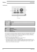
Страница 18: ...alve will make a short forced opening every three hours LED L2 indicates an alarm situation The test button can be used in three different ways When it is pressed during normal operation it starts a m...

Страница 19: ...when required Allows selection of the control mode See section Calling up modifying dryer regulation mode In order to control the dryer and to read and modify programmable parameters the controller ha...

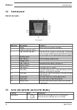
Страница 20: ...switched on 8 Service symbol 9 LED Service Is lit when service is needed 10 Start button This button starts the dryer Automatic operation LED 3 lights up The Infologic is operative 11 Stop button Thi...

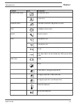
Страница 21: ...er is active Service Service required Units Temperature unit Temperature unit Hours The value shown must be multiplied by 1000 to get the actual value Other icons Motor Drain Flow switch on energy sav...

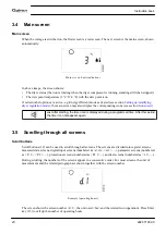
Страница 22: ...icon is displayed during a programmed time After this period the timer icon disappears again 3 5 Scrolling through all screens Scroll buttons Scroll buttons 12 can be used to scroll through all scree...

Страница 23: ...e timer settings P 5 Setting of the temperature unit See section Calling up Modifying unit of temperature P 6 Setting of the pressure unit See section Calling up Modifying unit of pressure P 7 Functio...

Страница 24: ...Description 1 Dew point main screen 13 Temperature unit 2 Ambient temperature 14 Pressure unit 3 Digital input status 15 Auto restart function 4 Running hours 16 Dryer regulation mode 5 Motor starts...

Страница 25: ...the ambient temperature is 25 C 77 F This temperature is used by the regulation algorithm to calculate a safe dew point in the energy efficient mode see section Calling up modifying dryer regulation m...

Страница 26: ...r in x1000 hrs hours x 1000 In above example the screen shows the dryer has been running during 100 hours 3 9 Calling up motor starts Calling up motor starts This screen shows the number of motor star...

Страница 27: ...Service warning A service warning will appear when the service timer has reached the programmed time interval See section Calling up modifying service timer settings If the service timer exceeds the p...

Страница 28: ...een with dew point temperature warning In the example shown the dew point is 20 C 68 F and the dew point icon is flashing If the dew point becomes normal again the alarm will disappear High ambient te...

Страница 29: ...pear as soon as the warning condition disappears 3 13 Shut down Description The dryer will shut down In case the dew point temperature gets below 0 5 C 31 1 F delay 30 s In case the ambient temperatur...

Страница 30: ...AN control To change press Enter button 13 and if necessary enter the password see section Activating password protection The actually selected control mode is blinking Use Scroll button 12 to change...

Страница 31: ...ed Change the function to OFF to change the node ID It is also possible to change the channels The controller has 4 channels When changing the channels the controller can act as a Mk IV controller a p...

Страница 32: ...Enter button 13 to modify it to OFF Use the Scroll buttons Up or Down 12 to scroll between the items in this list IP for IP address Sub for Subnetmask or GAtE for Gateway Modification Press the Enter...

Страница 33: ...Press Enter button 13 to modify this value a password may be required the value starts blinking Use the Scroll buttons 12 to modify the setting Press Enter button 13 to program the new value Press Es...

Страница 34: ...yer regulation mode Description The dryer has two regulation modes Regular mode The dryer achieves the lowest possible dew point Energy efficient mode The dryer will regulate the dew point between the...

Страница 35: ...and then press Enter key 13 the actual flow switch setting is shown StOP flow switch function is active or OFF flow switch function is not active Press Enter key 13 to modify this value a password may...

Страница 36: ...ce timer and control mode settings can be protected by a password Starting from the Main screen Press Scroll buttons 12 until P 10 is shown and press Enter button 13 Password PASS appears on the scree...

Страница 37: ...is blinking Use Scroll button 12 to change the alarm mode Press Enter button 13 to program the new alarm mode Press Escape button 14 to return to the parameter screens 3 26 Calling up modifying fixed...

Страница 38: ...difying the low dew point setting Calling up modifying the low dew point setting In protection parameter set Pr 2 the Low dew point alarm level AL L and the Low dew point shutdown level Sd L can be se...

Страница 39: ...95 F and 60 C 140 F Starting from the Main screen press Scroll button 12 until Pr 3 is shown and then press Enter button 13 AL H is shown Press Enter button 13 the programmed value starts blinking Use...

Страница 40: ...4 Installation 4 1 Dimension drawings QED 250 and QED 300 dimension drawing Instruction book 38 2920 7103 90...

Страница 41: ...350 up to QED 600 dimension drawing Reference Name 1 Main supply electrical cable gland M25 2 Manual drain 3 Automatic drain 4 Cooling air flow 5 Air inlet 6 Air outlet Instruction book 2920 7103 90...

Страница 42: ...4 2 Installation proposal Installation proposal QED 250 and QED 300 Instruction book 40 2920 7103 90...

Страница 43: ...Installation proposal QED 350 up to QED 600 Text on drawings Instruction book 2920 7103 90 41...

Страница 44: ...3 Make sure that no dirt particles e g coming from corrosion in the compressed air network can enter the dryer These particles may be harmful to the dryer s heat exchanger and the condensate drain 4 I...

Страница 45: ...3 Check the fuses and the setting of the overload relay See section Settings of fuses 4 On single phase units connect the power supply cables to terminals L1 L2 of terminal strip 1X0 5 On three phase...

Страница 46: ...units Typical designations used in the electrical diagrams Reference Designation 1 Customer s installation 2 Flow switch 3 Alarm EWD 4 Remote start stop B1 Electronic drain 1X0 6 Terminals F1 6 Fuses...

Страница 47: ...ase sequence relay K5 Auxiliary relay alarm functions M1 Compressor M2 Fan motor PSHH13 High pressure switch PSR12 Fan switch S1 Remote start stop S2 Flow switch X209 Connector 4 4 Pictographs Pictogr...

Страница 48: ...Reference Description 5 Warning voltage 6 Information label refrigerant Contains fluorinated greenhouse gases covered by the Kyoto Protocol Instruction book 46 2920 7103 90...

Страница 49: ...2 Initial start Procedure Control panel Step Action 1 A few minutes before starting the main supply to the dryer must be switched on to initialize the Infologic and the flow switch 2 Press start butto...

Страница 50: ...nd the flow switch to initialize 2 If installed close the dryer bypass valve and the dryer outlet valve customers installation 3 Open the dryer air inlet valve customers installation and pressurize th...

Страница 51: ...display of the control panel The pressure dew point will deviate from nominal if the air inlet conditions or volume flow differ from nominal That condensate is discharged The amount depends on the op...

Страница 52: ...1 Close dryer inlet and outlet valves customer s installation 2 Press stop button 11 The dryer stops Voltage on LED 4 remains lit Leave the voltage on if the dryer has to remain on stand by Instructio...

Страница 53: ...can reach a temperature of 110 C 230 F Therefore wait until the dryer has cooled down before removing the panels Before starting any maintenance or repair work switch off the voltage and close the ai...

Страница 54: ...off the supply voltage Remove the front service panel Remove dust from the condenser surface using a vacuum cleaner Clean the condenser by blowing compressed air from outside to inside Keep the compre...

Страница 55: ...ceeded Reduce air flow Shortage of refrigerant Have circuit checked for leaks and have the refrigerant circuit recharged Condition Fault Remedy Condenser pressure too high or too low Fan control switc...

Страница 56: ...m visible red light and blinking drain icon Condition Fault Remedy Drain alarm No pressure in the air net Error disappears when the pressure in the air net is restored Drain was not able to drain all...

Страница 57: ...ing K12 1 K12 3 Condition Fault Remedy High pressure switch has shut down the dryer Condensing pressure too high Push the small button of the high pressure switch Clean condenser Improve ventilation o...

Страница 58: ...ow the minimum pressure Ensure there is the minimum pressure The drain filter is blocked by dirt Open the manual drain valve to clean the drain filter The feed and or outlet line is shut off or blocke...

Страница 59: ...ons Unit 60 Hz Compressed air inlet pressure bar e 7 Compressed air inlet pressure psig 101 53 Compressed air inlet temperature C 38 Compressed air inlet temperature F 100 4 Ambient temperature C 38 A...

Страница 60: ...l power consumption including cooling fan 60 Hz kW 1 5 1 5 2 3 Total power consumption including cooling fan 60 Hz hp 2 28 3 22 3 08 Refrigerant type R410a R410a R410a Refrigerant charge approx kg 0 8...

Страница 61: ...Air dryer type Units QED 450 QED 500 QED 600 Dryer mass approx kg 197 197 197 Dryer mass approx lb 434 434 434 Instruction book 2920 7103 90 59...

Страница 62: ...an or equal to category II Dryer type Part number Description PED Class QED 250 up to QED 600 1089 9139 14 High pressure switch IV QED 250 and QED 300 1624 2274 00 Heat exchanger II QED 350 1624 2275...

Страница 63: ...laration of conformity Typical example of a Declaration of Conformity document 1 Contact address Quincy Compressor 701 North Dobson Avenue Bay minette AL 36507 United States Instruction book 2920 7103...

Страница 64: ......

Страница 65: ......

Страница 66: ...No 2920 7103 90 2011 11 Printed in Belgium Performance You Demand Reliability You Trust www quincycompressor com...

Отзывы: