108833 Rev. C
35
S - 6 3 6 / S - 6 4 6
XII. MAINTENANCE
E. PNEUMATIC TIRES
WARNING
1. Do not use this chair if any of the tires are under- or over-inflated.
2. Low pressure in a tire may cause the chair to veer to one side and result in
loss of control.
3. An over-inflated tire may burst.
4. Never use a gas station pump to inflate a tire. Such pumps provide air at high
volume, and may cause tire to burst.
1. Check for signs of wear and correct air pressure in pneumatic tires weekly.
2. For best performance, inflate tires to the same pressure level, as shown on the tire
sidewall:
•
8" pneumatic casters - 30 to 40 psi
•
14" pneumatic drive wheels - 35 to 45 psi for knubby tires and 25 psi for V-groove
tires.
3.
CAUTION
: To prevent tire damage:
• Use a hand pump (or a
low volume
air pump) to inflate tires.
•
Use a tire gauge to check pressure.
F. TO REPAIR OR REPLACE A TIRE
WARNING
Residual air pressure in tires can cause severe injury. Make sure you release all
air in tire before attempting to service or repair tires.
1. 8" Caster Wheels:
a) Release all air from tire.
b) Remove caster wheel from fork.
c) Make sure there is no residual air in tire before you remove bolts that hold the two
rim halves together.
d) Remove four bolts from rim. Separate two halves of rim.
e) Repair or replace inner tube.
f) Reassemble the caster wheel; makesure the bearing spacer is in place and all four bolts are
secure.
NOTE–
Use a torque setting of 240 inch-pounds when tightening bolts.
g) Mount caster wheel onto fork. Install washers correctly.
h) Inflate tire to proper pressure level.
2. 14" Drive Wheels:
a) Elevate and securely support chair so that wheel is off the ground.
b) Release all air from tire.
c) Remove the four lug nuts securing wheel to hub (this is necessary only if technician
desires to remove entire wheel assembly– not required).
d) Remove all bolts holding two halves of rim together.
e) Repair or replace inner tube.
f)
Reassemble wheel rim.
Use a torque setting of 180 lbs.-in. to re-tighten bolts.
g) Re-secure wheel to hub using four lug nuts.
Use a torque setting of 240 lbs.-in. to re-tighten lug nuts.
h) Inflate tire to proper pressure level (listed on tire sidewall).
It is recommended to operate chair for 10-15 hours and then re-verify installation
torque of lug nuts at 240 lbs.-in.
G. MOTOR BRUSHES
You should have your supplier check the motor brushes every four (4) months for wear. The
brushes should be clean and shiny. Replace worn or blackened brushes.
H. ORDERING PARTS
When you order parts, provide the following:
1. Model of chair
2. Serial number of chair
3. Left hand or right hand control
4. Part number, description and quantity of parts you need.
5. State reason for replacement.
Содержание S-636
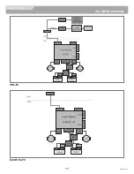
Страница 37: ...108833 Rev C 37 S 636 S 646 XIII WIRING DIAGRAMS VR2 90 R NET EL 90 ...
Страница 39: ...108833 Rev C 39 S 636 S 646 XIII WIRING DIAGRAMS SWITCH DRIVEN SINGLE ACTUATOR DRIVER R NET MULTI ACTUATOR ...
Страница 40: ...LIGHTS INDICATORS 108833 Rev C 40 S 636 S 646 XIII WIRING DIAGRAMS R NET MULTI ACTUATOR W O RECLINE ...

