108833 Rev. C
15
S - 6 3 6 / S - 6 4 6
K
IX. SET-UP, ADJUSTMENT, & USE
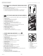
D.BATTERY REMOVAL
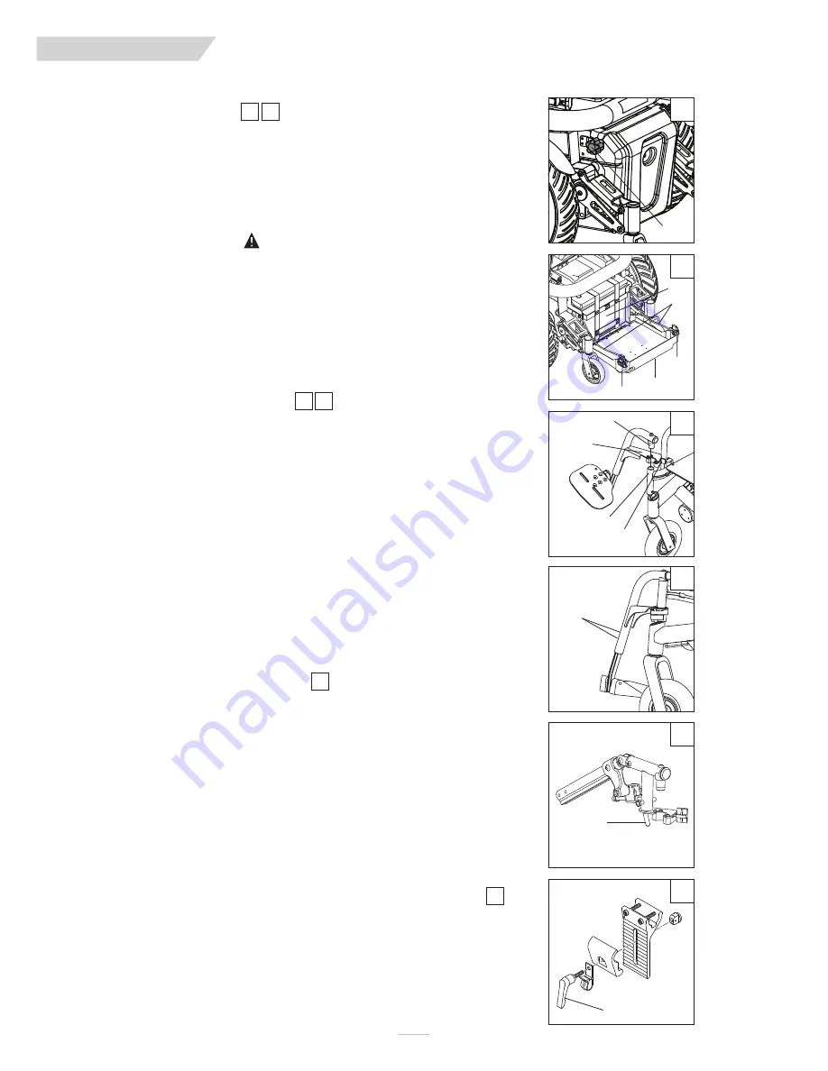
To remove batteries for transport or service:
1. Unscrew both the right and left battery box rear cover retaining fasteners (A).
2. Lower battery box rear cover (B) until the cover is fully extended and supported by
the cables (C).
3. Disconnect the battery harness cables.
4. Slide out batteries (D).
5. Remove batteries (D).
WARNING
Batteries may weigh up to 55 lbs. Care must be taken to avoid injury when lifting.
E. SWING-AWAY FOOTRESTS
1. Installation
a) Place swing-away pivot pin (E) into the locating hole (F) on top of the hanger mount
with the footrest facing outward from frame.
b) Rotate the footrest inward until latch plate locks (G) into place on locking bolt.
2. Removal
a) To remove footrest, press quick-release lever (H).
b) Rotate footrest outward and lift.
3. Height Adjustment
a) Loosen both bolts (I) in the hanger frame tube.
b) Reposition footrest height.
c) Re-tighten both bolts (I).
F. ELEVATING LEGREST
(OPTIONAL)
1. Installation
To install or remove Elevating Legrest (ELR) see instructions for Swing-away Footrest installation.
2. Adjustment
a) To raise legrest, lift to desired position. Legrest will automatically lock in place.
b) To lower legrest, while seated in chair, first lift slightly then press release lever (J) down
and lower legrest to desired position.
G. TO ADJUST THE HEIGHT OF THE REMOTE JOYSTICK
a) Rotate handle (K) to loosen the joystick mount.
b) Reposition joystick mount to the desired height and retighten the handle.
2
1
4
3
5
6
A
A
C
D
B
A
1
2
E
H
F
G
I
J
3
4
5
6
Содержание S-636
Страница 37: ...108833 Rev C 37 S 636 S 646 XIII WIRING DIAGRAMS VR2 90 R NET EL 90 ...
Страница 39: ...108833 Rev C 39 S 636 S 646 XIII WIRING DIAGRAMS SWITCH DRIVEN SINGLE ACTUATOR DRIVER R NET MULTI ACTUATOR ...
Страница 40: ...LIGHTS INDICATORS 108833 Rev C 40 S 636 S 646 XIII WIRING DIAGRAMS R NET MULTI ACTUATOR W O RECLINE ...


