108833 Rev. C
25
S - 6 3 6 / S - 6 4 6
X. OPERATING INSTRUCTIONS
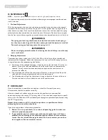
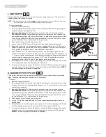
5. Joystick (G)
The joystick controls the direction and speed of your chair. Turn the chair on and move the
joystick in the direction you want to go.
• Moving the joystick from the neutral (center) position disengages the motor brakes,
allowing the chair to move.
• The chair will move faster the more you move the joystick away from neutral.
NOTE–
If your speed becomes hard to manage, release the Joystick and the chair will come to a complete
stop.
• When you release the joystick it will return to neutral; the chair will slow to a stop and
the motor brakes will reengage.
• We recommend that you switch the chair off if you stop for any length of time. This
will conserve battery power.
NOTE–
Once the chair stops, switching the chair off will not affect the motor brakes.
6. Joystick Boot (H)
Make sure the boot is not torn or cracked (this could allow debris, water or moisture to
enter). If the boot is torn or cracked, replace it as soon as you can.
7. Tilt Control (SC only) (I)
This button once depressed allows you to control the up and down movement of the tilt. Press
button “I”. Then pull the joystick back to tilt the seat upward or push the joystick forward to
tilt the seat downward. Pressing button “I” again will allow drive operations to resume.
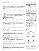
F. R-NET JOYSTICKS & OMNI CONTROLLER
Controls:
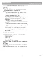
• LED monochrome joystick and color display joystick
Omni Input/Display
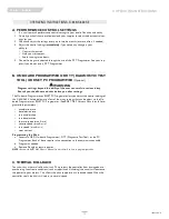
The Omni is a universal specialty controls interface that accepts signals from many different
types of SIDs (Specialty Input Device) and translates them into commands compatible with
the PG Drives Technology RNET control system.
Mating Connectors
To connect the communication cables:
Holding the connector housing, firmly push the connector into its mate until you can
no longer see the yellow plastic. The connectors are secured using a friction system.
To disconnect the communication cables:
Holding the connector housing firmly, pull the connectors apart.
NOTE–
Do not hold or pull on the cable. Always grip the connector when connecting and disconnecting.
When the control system is first switched on after a connection, or system component
change, the timer will be displayed while the system checks itself. Then the re-start icon will
be displayed. Switch the control system off and on again to operate,
3
4
5
6
4
5
6
power
module
LCD screen
Profile
+/-
Navigation
Mode
On/Off
LED
Color
joystick
communication
cable
Omni Display
Monochrome
Joysticks
3
4
5
6
Содержание S-636
Страница 37: ...108833 Rev C 37 S 636 S 646 XIII WIRING DIAGRAMS VR2 90 R NET EL 90 ...
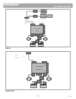
Страница 39: ...108833 Rev C 39 S 636 S 646 XIII WIRING DIAGRAMS SWITCH DRIVEN SINGLE ACTUATOR DRIVER R NET MULTI ACTUATOR ...
Страница 40: ...LIGHTS INDICATORS 108833 Rev C 40 S 636 S 646 XIII WIRING DIAGRAMS R NET MULTI ACTUATOR W O RECLINE ...

