I
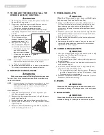
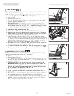
VR2 Joystick with Actuator
Control
A
D
F
G
H
B
E
C
VR2 Joystick
108833 Rev. C
24
S - 6 3 6 / S - 6 4 6
X. OPERATING INSTRUCTIONS
D. JOYSTICK STATIONARY
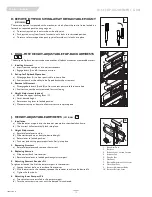
Your chair has an available programming feature called “Joystick Stationary” which can be set by
your dealer. This feature senses when the joystick is displaced from neutral, yet left in a steady
position for a predetermined period of time. The controller will automatically turn off if the set
time has been reached. This feature is designed to protect the user, batteries and electronics if
the joystick is inadvertently displaced. There are two parameters that can be adjusted:
1. Joystick Stationary Time:
This is the time the joystick has to remain within the stationary range before the unit
will come to a stop. It can be programmed from 0 to 60 minutes in steps of one
minute. Select 0 to disable the function. Default setting is 0 (Disabled).
2. Joystick Stationary Range:
This determines the size of a region around the present joystick position. If the joystick
remains within this region for the stationary time the controller will stop. The range
can be programmed from 1 to 50, in steps of 1. Default setting is 1.
WARNING
Before turning on or adjusting these parameters, carefully read and understand
the implications for use of these features, Joystick Stationary Time and Joystick
Stationary Range. When the “Joystick Stationary Time” is reached within the
“Joystick Stationary Range”, the drive motors on the chair will shut off. As an
example, this will happen while driving in a straight line for extended periods of
time with no joystick movement. Once the drive motors turn off, the user will
need to turn the chair off and back on to drive.
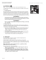
E. VR2 JOYSTICK ASSEMBLY
The standard VR2 joystick controls the chair’s performance. It consists of the following parts:
1. Speed Control or Drive Mode Selection Buttons (A and B)
To decrease the speed level depress button A. Or, when 1- 5 Drive modes are programmed,
depress button A to activate lower drive mode(s).
To increase speed level, depress button B. Or, when 1- 5 Drive modes are programmed,
depress button B to activate higher drive mode(s).
Speed level active, or Drive Mode selected, is indicated on display (C) by a series of five
lights. One light indicates slowest level/mode currently active, while five lights indicates high-
est level/mode currently active.
2. Battery Charge Indicator (D)
• Green lights indicate that batteries are fully charged.
• Yellow lights indicate that batteries need recharging.
• When the lights stay in the red band, the batteries must be recharged.
3. On/Off Button (E)
Turning the chair on or off is accomplished by depressing button E.
4. Horn (F)
1
2
1
2
Содержание S-636
Страница 37: ...108833 Rev C 37 S 636 S 646 XIII WIRING DIAGRAMS VR2 90 R NET EL 90 ...
Страница 39: ...108833 Rev C 39 S 636 S 646 XIII WIRING DIAGRAMS SWITCH DRIVEN SINGLE ACTUATOR DRIVER R NET MULTI ACTUATOR ...
Страница 40: ...LIGHTS INDICATORS 108833 Rev C 40 S 636 S 646 XIII WIRING DIAGRAMS R NET MULTI ACTUATOR W O RECLINE ...


