ENGLISH
30
Life RT Rev.J
DANGER!
•
Before using your wheelchair ensure the lap belt is worn.
•
The lap belt must be checked on a daily
•
basis to ensure it is free from any obstruction or adverse
wear.
•
Always make sure that the lap strap is correctly secured
and adjusted prior to use. If the strap is too loose it could
cause the user to slip down and risk suffocation or cause
serious injury.
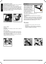
The lap belt is fitted to the wheelchair as shown in the
illustrations. The seat belt comprises 2 halves. They are fitted
using the existing seat stay retaining bolt fitted through the
eyelet on the belt. The belt is routed under the rear of the side
panel. (Fig. 6.44)
Adjust the belt position so buckles are in the centre of the seat.
(Fig. 6.45)
Pelvic Restraint Belt
Fig. 6.44
Fig. 6.45
Adjust lap belt to suit the user’s needs as follows:
To reduce the belt
length
To increase the belt length
Feed free belt
back through male
buckle and slide
adjusters.
Ensure belt is not
looped at male
buckle.
Feed free belt through slide adjusters
and male buckle to provide more belt
length.
When fastened check space between the pelvic restraint belt
and user. When correctly adjusted it should not be possible to
insert more than the flat of the hand between the lap belt and the
user. (Fig. 6.46)
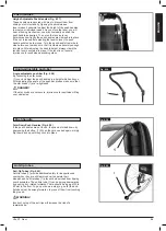
Crutch Holder
Crutch Holder (Fig. 6.41)
This device permits crutches to be transported directly on a
wheelchair. It has a Velcro loop to fasten crutches or other aids.
CAUTION!
Never try to use / remove the crutches or other aids while
moving.
Fig. 6.41
Headrest
Headrest (Fig. 6.42)
The headrest can be raised and also moved horizontally both
forwards and backwards.
To do this, loosen the screw (1, 2 or 3).
Now you can adjust to the desired position. Tighten screws
again (see the page on torque).
To fold the wheelchair (Fig. 6.43)
In order to fold the wheelchair, please open the clamping lever
(1), slide the headrest bracket to the right side and fold it down.
Now you can fold the chair. To unfold the chair, please fold the
headrest bracket up, re-position the sliding gap into the
clamping lever and slide it to the left. Finally close the clamping
lever again.
Fig. 6.42
3
1
2
Fig. 6.43
1
1


