background image

5

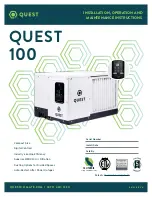
QUEST 100 


                                                   INSTALLATION, OPERATION AND MAINTENANCE INSTRUCTIONS

QUESTCLIMATE.COM

(877) 420-1330

4.  INSTALLATION

4.1  LOCATION

The Quest 100 Dehumidifier can be installed in a variety of locations to meet the owner’s needs as listed 
below. In all cases keep the following cautions in mind:

•  Locate the dehumidifier near a suitable drain (8’ drain hose included). Allow for proper drainage and 

routing of needed drain pipes.

•  Locate the dehumidifier in an area where the cord’s length (9’) easily reaches a 115 VAC electrical 

outlet with a minimum of a 15 Amp circuit capacity.

•  The unit is designed to operate while level. If the unit is placed on an unlevel surface, refer to section 

below (Installing Leveling Feet). Failure to level the unit may result in leakage or improper drainage.

•  Allow sufficient clearance to handle the unit’s overall dimensions as well as any optional return and 

supply ductwork to the unit.

•  Allow sufficient clearance for filter removal and to prevent airflow obstruction.

•  Electrical service access will require the removal of the top “L” shaped panel. Allow sufficient 

clearance around the unit.

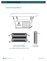
•  The Quest 100 Dehumidifier may be suspended with steel hanger, straps, or a suitable alternative 

from structural members, unit must be supported from underneath. Don’t hang from sides or ends. 
See section 4.4 

•  The unit should be suspended with a hang kit from the floor joists if there is any possibility of 

flooding. A flooded unit is not covered by warranty. Feet will be installed as a securing measure after 
the hang kit is put on the dehumidifier. DO NOT hang the Quest 100 dehumidifier from its’ cabinet.

4.2  DUCTING

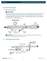
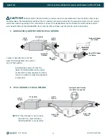
Return and supply duct collars are optional accessories for the Quest 100 and not included with the unit.


CAUTION! 

Do not connect with a static pressure greater than or equal to +1.0 WG. Contact 

technical support at (877) 420-1330 for additional details.

DUCTING CONSIDERATIONS:

  All flexible ducting connected to the Quest 100 should be UL listed.
•  A short piece of flexible ducting on all Quest 100 duct connections is recommended to 
  reduce noise and vibration transmitted to rigid ductwork in the structure.
•  Use a minimum 10” diameter round or equivalent rectangular duct for total duct 

lengths of up to 25’.

•  Grills or diffusers on the duct ends must not excessively restrict airflow.

• A length of 8” or more of insulated flex duct or any other vibration isolating material on the  


  outlet of the


Quest 100 will reduce air noise from the blower.

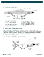
• When ducting two or three areas, use 8” or larger diameter branch ducting. When ducting to four or  
  more areas, use 6” or larger diameter branch ducting. Provisions must be made to provide airflow


supply locations to the central return location. Proper air distribution is important to ensure even  


humidity control and heat distribution throughout the structure. 

Содержание 100

Страница 1: ...O M 87 7 420 1330 Patents thermastor com patents Serial Number Install Date Sold By 06 23 R E V A Compact Size Digital Controls Industry Leading Efficiency Superior MERV 13 Air Filtration Ducting Opt...

Страница 2: ...rd Air Filter 14 6 2 Impeller Fan Oiling 14 7 Service 15 7 1 Warranty 15 7 2 Technical Description 15 7 3 Troubleshooting 15 7 4 Refrigerant Charging 17 7 5 Impeller Fan Replacement 17 7 6 Compressor...

Страница 3: ...able DO NOT place the device directly on structural members Provide vibration isolation in order to minimize operational vibration and or noise A drain pan MUST be placed under the unit if installed a...

Страница 4: ...AGE 120 Volt 1 Phase 60 Hz CURRENT DRAW 5 0A RATED CURRENT DRAW 104 F 36 6 8A MINIMUM CIRCUIT AMPACITY MCA 8A MAXIMUM OVERCURRENT PROTECTION MOP 15A RECOMMENDED BREAKER SIZE 15A ENERGY FACTOR L KWH 3...

Страница 5: ...4 4 The unit should be suspended with a hang kit from the floor joists if there is any possibility of flooding A flooded unit is not covered by warranty Feet will be installed as a securing measure a...

Страница 6: ...year as this could diminish the water removal capability of the dehumidifier If the Check Damper is not used it is important to have the HVAC system fan ON when the dehumidifier is ON to prevent backf...

Страница 7: ...local codes prior to installing C DEDICATED QUEST RETURN TO HVAC RETURN Create a separate return for the Quest 100 Dehumidifier in a central area of the building Installing the supply air from the Qu...

Страница 8: ...e dehumidifier Install a 6 insulated duct from outside teeing into the 8 return duct of the Quest 100 Dehumidifier to provide outdoor air ventilation optional An 8 diameter duct is recommended for bra...

Страница 9: ...ore Be sure the extension is at a downward slope to the drain B An optional condensate pump kit may be installed if lift is required to remove condensate To order contact your local dealer or visit ou...

Страница 10: ...ERATION AND MAINTENANCE INSTRUCTIONS QUESTCLIMATE COM 877 420 1330 4 4 HANGING DIAGRAM QUEST 100 4036668 Hang Bracket PN 4036668 Bottom view of dehumidifier and two brackets not included NOTE LEVELING...

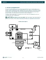
Страница 11: ...area that may become wet a GFCI protected circuit is recommended The unit should not be used in areas prone to flooding Consult local electrical codes for any further information An optional remote de...

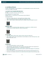
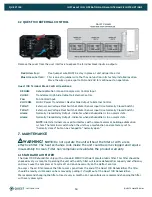
Страница 12: ...over the snowflake will light up when defrost is occurring ice is detected on coils The fan will be on and the compressor will be off during defrost FILTER RESET Filter reset button will light up afte...

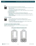
Страница 13: ...ated when an external control is used to control RH When Terminal Control is active the internal RH sensor is disabled Pressing the Fan button alternates the unit between 3 fan speeds Hi gh Increased...

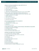
Страница 14: ...t Indicates when dehumidifier is in an alarm state NOTE Alarm terminals are used to interface with a remote alarm or building automation system The terminals switch when the unit has a malfunction and...

Страница 15: ...l where it absorbs heat from the incoming air and evaporates The evaporator operates in a flooded condition which means that all the evaporator tubes contain liquid refrigerant during normal operation...

Страница 16: ...ntrol or power board Fan is not running Dehumidification or fan is being called for 7 Loose connection in fan circuit 8 Obstruction prevents fan impeller rotation 9 Defective fan 10 Bad control or pow...

Страница 17: ...trical components 2 Plug in the unit and turn the humidity control to ON Check for volts from compressor black wires on compressor relay to white wire on compressor capacitor using an AC voltmeter 2 1...

Страница 18: ...r was not rotating Contaminants are therefore largely confined to the compressor housing A single installation of liquid and suction line filter driers will probably clean up the system If sludge is e...

Страница 19: ...ator it will sense the frost build up and automatically defrost the evaporator The Quest 100 Dehumidifier may not appear to be operating correctly during the defrost sequence but once the defrost sequ...

Страница 20: ...service people should service this unit TOOLS REQUIRED T25 Torx Driver 11 32 Driver Following all local and national electrical codes and standards route electrical service to the location that the de...

Страница 21: ...ound stud and use 11 32 driver to secure nut to stud Connect WHITE wire from LINE N terminal Connect BLACK wire from LINE L terminal Remove cord retention bracket Remove bushing from 7 8 hole 9 Replac...

Страница 22: ...6 TEMPERATURE TOO HIGH Error code E6 compressor off fan off Temperature too high Broken sensor Yes 7 TEMPERATURE TOO LOW Error code E7 compressor off fan off Temperature too low Broken sensor Yes 8 C...

Страница 23: ...use abuse lack of normal care corrosion freezing tampering modification unauthorized or improper repair or installation accident acts of nature or any other cause beyond Therma Stor LLC s reasonable c...

Страница 24: ...1 Comm Cable 7 4039294 Condenser 8 4039814 Compressor 9 4039815 Overload not pictured Item Part No Description 10 4041909 Display Assembly 11 4042005 Filter 12 4042066 01 Impeller 13 4042119 01 Base D...

Страница 25: ...25 QUEST 100 INSTALLATION OPERATION AND MAINTENANCE INSTRUCTIONS QUESTCLIMATE COM 877 420 1330 3 7 8 9 10 1 4 5 11 14 13 12 16 17 2...

Страница 26: ...QUESTCLIMATE COM 877 420 1330...

Отзывы: