QUATRO
Air Technologies Inc.
Fresh Air Purifiers
-----------------------------------------------------------------------------------------------
Engineers Of Clean Air
8.2
PARTICULATE FILTER REPLACEMENT
a)
Open the filter access door with the appropriate tool (Phillips screw driver) to avoid stripping of screws;
b)
Carefully slide pre-filters and high capacity filters along their support channels, Slide clean filters gently into place;
c)
Ensure Dust Filters are replaced as per airflow indications;
e)
If encountering difficulties, confirm that there are no obstructions in the filter track;
f)
Hi-Efficiency filters must be replaced as per airflow arrow on the filter casing;
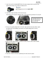
g) HEPA filters should be installed with gaskets facing up to seal on the section above the filter.
For critical applications, a secondary seal can be applied using continuous bead of removable sealant. (Part# AR321)
This would be applied to the middle of the gasket in a continuous bead prior to putting the HEPA into the system and then
Inserting pressure seal rods
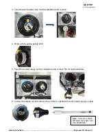
h) The RNP systems are equipped with a HEPA pressure sealing mechanism. The easiest and most effective way to change the HEPA filters is
with the unit lying down on its back. Two or more people will be required to do this safely. Once lying down the pressure sealing mechanism rods
are to be pulled out to release the seal. There are loops on the rods to help pull. If it is difficult to remove please use a tool for additional leverage.
Please note it critical for these filters to be tight and secure to avoid by-pass so this is completely normal. If secondary sealant was applied please
remove this prior to installing new filter.
i)
Care must be taken not to damage the exposed portions of the new HEPA filter. DO NOT bend aluminium separators as this will obstruct airflow.
j)
RESET
“Service Filter(s)” Light (see section 8.6)
8.3
Optional CHEMICAL FILTER TRAY (F003) MAINTENANCE
It is essential that the chemical filter media be replaced approximately every twelve months
OR
immediately following any detection of odor. After an
operating period of twelve months (or when the filters are consumed), call your authorised distributor to purchase a new set of chemical filtration
assemblies (Part No: F003-xxx ) prior to removal of existing one.
To replace Odor Filter (Part No: F003-xxx)
a)
Ensure that the unit is unplugged, open door with appropriate tool to avoid stripping of screws;
b)
Slide out the existing F003 chemical module, remove new F003 from the box that it was shipped in;
c)
Reinsert new filter back into the system with removable lid on top;
d)
Return door to the closed position and verify that an airtight seal is maintained;
e)
RESET
“Service Filter(s)” Light (see section 8.6)
8.3
Optional BULK CHEMICAL MEDIA FILTER TRAY (F003) MAINTENANCE
To refill existing F003 chemical filter cell with new bulk odor media:
a)
Slide out existing F003 filter (see diagram below);
b)
Unscrew the screws and lift off access cover;
c)
Pour out used odor filter (
this procedure may be dusty, therefore it is recommended to do this in a well-ventilated area. It is also
recommended to wear a dust mask, goggles and gloves when replacing bulk media)
;
d)
Refill F003 container with fresh odor filters and replace the 2 panel covers and re-insert into unit as per diagram on last page of manual;
e)
RESET
“Service Filter(s)” Light (see section 8.6)
Filter disposal is the responsibility of the end-user. Please contact local authorities for proper and legal disposal.


