9
and yellow are the primary colors of the subtractive
system. So far the theory (again). In practice, a sub-
tractive cyan looks much different than an additive
cyan. And an additive red looks even more different
than a subtractive red.
However, to make sure that a display shows the right
white and the behaviour of all three channels at any
luminance is correct, a display needs to be adjusted.
Ways of Calibration
The color depth of a graphic signal from the compu-
ter to the display is 8bit - means 16.7 million colors
or 245 shades per channel. If this signal is changed,
the number of colors will be lower the bigger the
change will be. Therefore the best way is to avoid any
corrections of the signal. But as we have learned, a
display needs to be adjusted to show colors correct-
ly. That means the corrections have to be either done
in the displays or on the computer.
If the signal is corrected on the computer (in the
Look Up Table [LUT] of the graphics card), the signal
to the display does no longer contain the full 8bit
bandwidth. This will result in a loss of detail and
choppy gradiants. Up to 20% per channel or 50% of
all colors will be lost.
A better way is to correct as much as possible inside
the display and let only the remaining deviations be
corrected by the graphic card LUT. The loss can be
reduced to 10% per channel or 25% of all the colors.
However, the best way is to do all corrections inside
the display and also correct the non-linear behaviour
there. This will help to keep the full bandwidth. To do
so, a dedicated interface is needed to communicate
with the display. This approach is called hardware
calibration, while the first two ways are called soft-
ware calibration.
The hardware-calibrated Quato displays either use
USB or DDCI to communicate with the software on
the computer and adjust the displays internally with
up to 16bit precision. The high-precision LUT inside
the display is then used to correct all the deviations,
and the signal is downscaled to 10bit when it passes
the internal display driver circuits. The scaling can
be compared with high-end photography where
images are kept in 16bit mode until all corrections
have been done. Then, a scaling to 8bit shows no
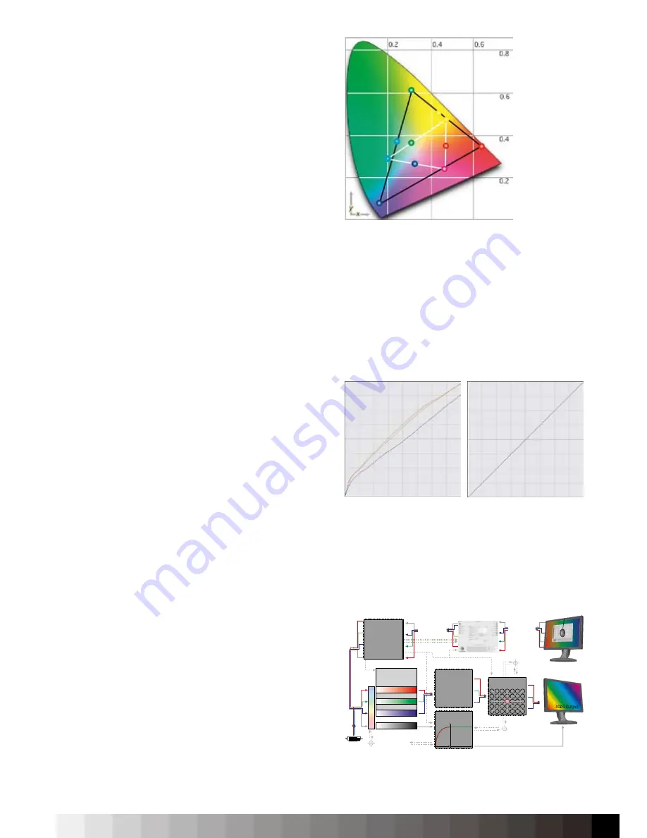
Subtractive system (white) and additive system (black)
LUT correction on the graphic card (left) versus correction inside
the display LUT (right)
Calibration
Processor with
16 bit per Channel
Embedded RISC
MCU
16 bit Color-
management
Routines
USB Interface
16
bi
t P
ro
K
an
al
16 bit Red LUT
Image
Enhancement
Processor with
Frame Modulation
for 30bit
16 bit Green LUT
Luminance
Stabilisation
16 bit Blue LUT
16
b
it
on
1
6
bi
t B
as
is
Gamma Correction
Whitepoint
Color Correction
Feedback Channel
45min
Lu
m
in
an
ce
Luminance-
Stabilisation
Uniformity Circuit
with 140 Measurements
Luminance Sensor
Uniformity Sensor
Temperature Sensor
�
DVI
30bit Output
Schematics of the process of a hardware calibration.
Содержание iColor Display 3.7
Страница 1: ...iColor Display 3 7 Intelli Proof Displays Manual ...
Страница 13: ...13 ...
Страница 17: ...17 ...
Страница 22: ...22 Intelli Color 190 Intelli Color 201 and 213 Connection Layout ...
Страница 23: ...23 Intelli Proof 190 and 201 Intelli Proof 213 and 213 excellence ...
Страница 27: ...27 ...
Страница 41: ...41 This page has been intentionally left blank ...
Страница 67: ...67 ...
Страница 68: ...68 ...
Страница 69: ...69 ...
Страница 70: ...70 ...
Страница 71: ...71 ...
Страница 72: ...72 ...
Страница 73: ...73 ...


