MINISYSTEM Manual Version 1.5
Page 1
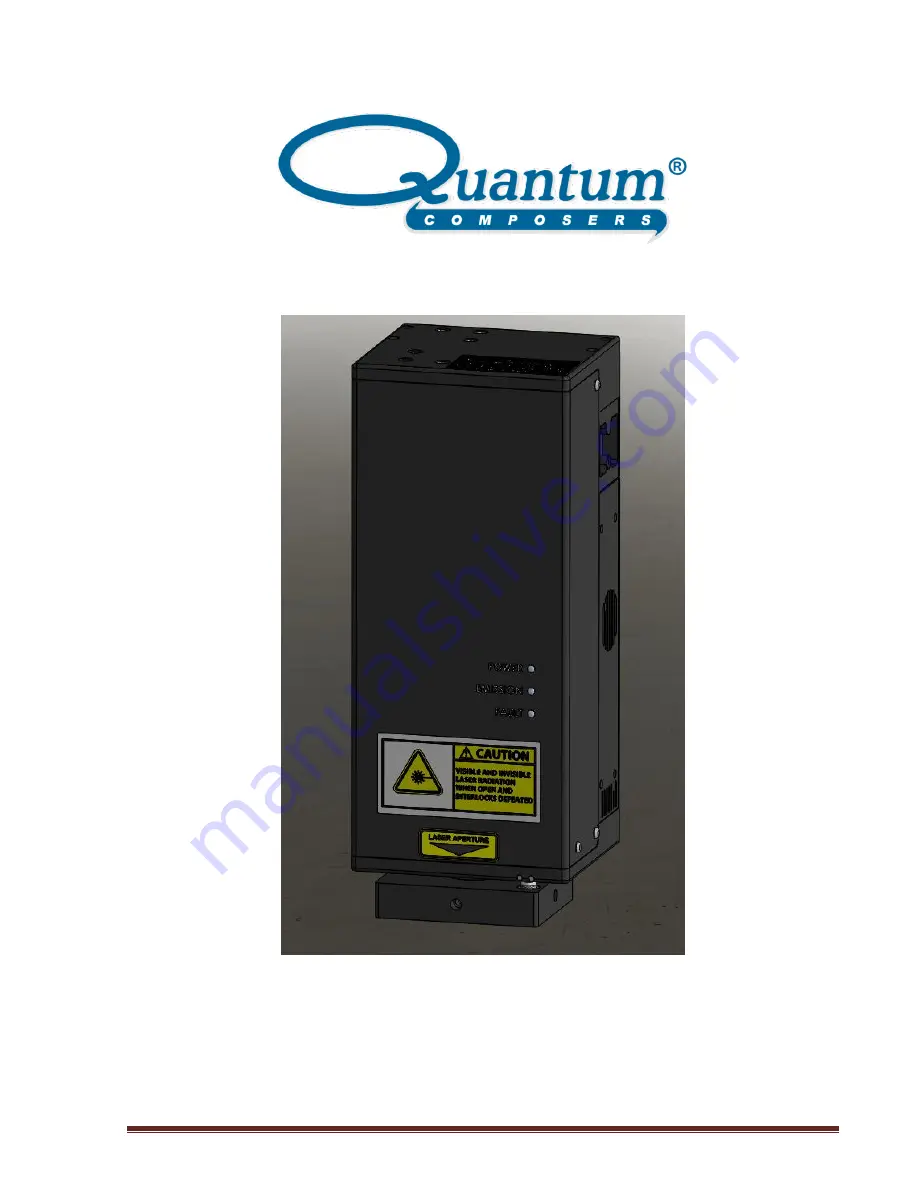
MINISYSTEM Laser System
Operating Manual
QUANTUM COMPOSERS, INC
PO Box 4248
Bozeman, MT 59772
(406)582-0227 phone
(406)582-0237 fax
www.quantumcomposers.com
Страница 1: ...MINISYSTEM Manual Version 1 5 Page 1 MINISYSTEM Laser System Operating Manual QUANTUM COMPOSERS INC PO Box 4248 Bozeman MT 59772 406 582 0227 phone 406 582 0237 fax www quantumcomposers com...
Страница 2: ...cking the Laser System 16 System Inventory 16 System Installation 17 Payload Setup 17 Laser System Setup 18 Optional System Connections 18 System Indicators 19 Authorized operation 19 Initial Power On...
Страница 3: ...Calibration Commands 32 8 MAINTENANCE 33 9 TROUBLE SHOOTING 33 No Laser Output 33 Energy is Low 33 10 SPECIFICATIONS 34 miniSystem Laser Specifications 34 Attenuator 34 X Y Slit 34 Theta Slit 35 Filte...
Страница 4: ...ached via one of the following methods Phone 1 406 582 0227 Fax 1 406 582 0237 Internet www quantumcomposers com Warranty The miniSystem has a one year limited warranty from the date of delivery This...
Страница 5: ...chapter contains essential information and user guidance about these hazards This product complies with safety standards EN61010 1993 A2 1995 EN60825 1994 A11 1996 and CDRH21 CFR 1040 10 d Do not ins...
Страница 6: ...utions for Safe Operation of Class 4 OEM Lasers Keep the protective covers on the Laser Head as much as possible Do not operate the laser with the covers removed for any reason Avoid looking at the la...
Страница 7: ...of Federal Regulations Chapter 1 Subchapter J Parts 1040 10 as applicable and with EN60825 1 1994 Part 1 for a Class 4 laser as applicable To maintain compliance verify the operation of all features l...
Страница 8: ...could provide a good ground return path Never work alone Someone should always be nearby to render aid if necessary Training in CPR first aid is highly recommended Electrical Safety CAUTION Both the...
Страница 9: ...704 USA Phone 303 792 2181 Safety Labels and Locations The following figures show the safety labels model number serial number and origination labels and their locations on the miniSystem Laser System...
Страница 10: ...MINISYSTEM Manual Version 1 5 Page 10 Figure 4 Cover Exposure Label Figure 5 Non Interlocked Cover Label Figure 6 Model Serial and Origination Label Figure 7 MINISYSTEM Safety Labels Front...
Страница 11: ...MINISYSTEM Manual Version 1 5 Page 11 Figure 8 MINISYSTEM Safety Labels Back...
Страница 12: ...gram which consists of the Jewel Laser the laser optic modules and the System Power Supply Figure 9 System Block Diagram Laser System Power Supply The portable power supply contains an AC DC converter...
Страница 13: ...ify the output of the laser head providing wavelength selection energy control beam sizing and beam shaping The payload also contains a Laser System Control LSC card which provides an interface to the...
Страница 14: ...is the attenuator The attenuator is used to control the amount of energy exiting the payload The attenuator is designed with a waveplate polarizer to provide motorized attenuation of the laser beams f...
Страница 15: ...ugh the 2nd mirror of the Parallel Mirror assembly to illuminate the XY Aperture When mounted in a system with the appropriate video optics the aperture can easily be viewed indicate where the laser c...
Страница 16: ...ly The system has undergone extensive testing to verify its conformance to the specifications prior to delivery Before operating the laser however it is important to fully understand its main features...
Страница 17: ...e voltage rating is marked on the Laser System Power Supply Operating the system at the incorrect voltage may result in damage to the unit CAUTION Ensure that the Mains power outlet that the Laser Sys...
Страница 18: ...ch such as a door or access panel If not used the shorting jumper must be connected When opened the system will indicate an interlock fault and stop firing the laser 2 Sync The sync connection is an o...
Страница 19: ...sword has been entered the user no longer has to re enter the correct password as long as the system remains on and the application software has not been closed The master password and the default use...
Страница 20: ...d not be used in close proximity to the Laser Optics Assembly since these substances will outgas and could contaminate the output window causing laser damage Avoid back reflections Back reflections of...
Страница 21: ...to the USB port on the Laser System Payload Start the LSxxx software The miniSystem application startup screen will be displayed as shown in Figure 14 This application has been designed as a graphica...
Страница 22: ...The laser will output 1 single laser pulse when the Fire button is pressed c Burst mode The laser will output the number of laser pulses specified by the Burst Count parameter The laser will stop firi...
Страница 23: ...is determined by the aperture size range 0 to max size divided by the microscope objective magnification The max size of the aperture is specified at time of order The system ID query will tell you wh...
Страница 24: ...Data 4 Ground Power Return Device Command Format All commands use ASCII characters and are composed of the following fields Prefix Address Delimiter Command String Parameters Terminator Field Descrip...
Страница 25: ...d is a recognized command and the parameter is valid then the device returns an OK CR If the command is not recognized then the device responds with a 1 CR If the command is recognized but the paramet...
Страница 26: ...and queries A CR indicates the carriage return value appended The system will initialize itself on power up There is no need to home any motors or stages The system will power up with the last saved...
Страница 27: ...LC IL 1 200 CR Response OK CR Description Sets the backlight illumination to 20 on The system is now ready to fire the laser Command to send LC FL 2 CR Response OK CR Description Starts the laser firi...
Страница 28: ...sponse OK CR Description Sets wavelength to DUV level to high energy to 50 polarization to 0 degrees and slit to 1mm x 1mm Various System Status Checks To check to see if the laser is ready to be enab...
Страница 29: ...d and allow enabling and firing the laser A query will return the unlocked state of the laser 1 unlocked 0 locked See the Authorized Operation section for the codes RDY Ready to Fire This query will s...
Страница 30: ...4 where 1 IR 2 GRN 3 UV 4 DUV Second parameter selects High 1 or Low 0 High mode gives 100 of full scale and Low mode is 25 of full scale Third parameter is Energy Density 0 1000 Where 1000 equals th...
Страница 31: ...from 1 50 Hz A query will return the current rate SC Shot Count Queries the laser accumulated shot count SW SW Select Wavelength Selects the wavelength to control Range is 1 to 4 where 1 IR 2 GRN 3 UV...
Страница 32: ...ibration Maximum Parameter is the measured energy when the output energy is set to 50 level using the ECS command NOTE This will be measured at high energy mode only and will be done for each waveleng...
Страница 33: ...er Optics Assembly and the Laser Power Supply Make sure all connections are secured If any of the cables are not installed properly the system will not function Check Energy Setting Check to see that...
Страница 34: ...e Width 1064 nm 6 0 2 0 ns Full width half maximum 532 nm 6 0 2 0 ns 355 nm 5 0 2 0 ns 266 nm 5 0 2 0 ns Pulse to Pulse Stability full aperture 50 25 10 1064 nm 4 8 10 12 RMS pulse to pulse stability...
Страница 35: ...nge of travel Initialization 6 0 s From power up System Specification Notes Size Payload 140 mm x 87 mm x 233 mm With optional video port Power Supply 132 mm x 58 mm x 31 mm Weight Payload 3 5 kg Powe...
Страница 36: ...ovided that the product is returned shipping prepaid to Quantum Composers All replaced parts and products become the property of the manufacturer This warranty does NOT extend to any lasers which have...