9530/8530 Manual Version 4.5
Page 39
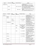
Keyword:
Command:
Sub-
Command:
Parameter
Range:
Notes:
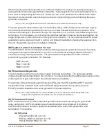
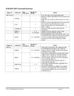
:PULSe[0]
Command to change the units’ global settings, this
is the same as using the :SPULse command
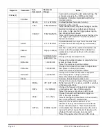
:OCLock
T
0
/ RATE /
CHAN / AUX1-4 /
DIS
Allows the user to select the clock source to output:
When ICLock is INT:
T
0
is the user defined period.
Rate = N/A
CHAN = N/A
AUX1 = 40 MHz
AUX2 = 20 MHz
AUX3 = 10 MHz
AUX4 = 5 MHz
When ICLock is in EXT:
T
0
is disabled
RATE =
f
output
will be
f
input
CHAN =
f
output
will be 2x
f
input
AUX1 = 2x EXT PLL
AUX2 = 1x EXT PLL
AUX3 = 1/2 EXT PLL
AUX4 = 1/2 EXT
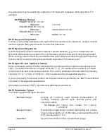
:GATe
Command to change the units’ global gate settings.
:MODe
DIS / PULS /
OUTP / CHAN
Sets the global gate mode for the unit: When in
pulse inhibit mode if the pulse has started before
the gate is seen the output pulse will finish, but any
further pulses will be prevented, In output inhibit
mode if a pulse has started it will be truncated as
soon as the gate signal is seen and will prevent any
further pulses, and when in channel mode each
channel can be setup individually (be aware of
insertion delay for each mode, this is listed in the
appendix)
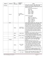
:LOGic
LOW / HIGH
Choose active Low (will allow pulses when low) or
active High (will allow pulses when high)
:EDGe
RISing / FALLing
Choose the edge of the incoming pulse to trigger
on. (Only used when the option for the gate to be a
second trigger input is enabled)
:LEVel
.20 – 15[V]
Choose the gate level threshold to trigger on, this
should be set to ~ 50% of the input potential
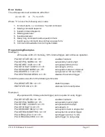
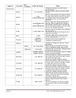
:TRIGger
Command to change the units’ global trigger
settings.
:MODe
DIS / TRIG /
DUAL
Sets the global trigger mode for the unit:
When the unit is set to single pulse each trigger
input will produce a output pulse, When in burst
mode each trigger input will produce a burst of
output pulses, and when in continuous or duty
cycle mode the trigger input will start the pulses
(the trigger will function the same as pressing the
Run/Stop button)
*Note: When in dual trigger mode each channel will
have the option to select which trigger to use.
:EDGe
RISing / FALLing
Choose the edge of the incoming pulse to trigger
on.
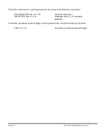
:LEVel
.20 – 15[V]
Choose the gate level threshold to trigger on, this
should be set to ~ 50% of the input potential.

