background image

6

09/20

7074-803C

C. Tools And Supplies Needed

B. Thermostat Wall Control Location

The thermostat wall control’s location will have some affect 

on the appliance’s operation.

•  Maximum wire length from appliance is 100 feet 

(30.48m) continuous non-spliced wire. Recommended 

20 gauge wire, solid copper

.

•  When located close to the appliance, it may require a 

slightly higher temperature setting to keep the rest of 

the house comfortable.

• 

When located in an adjacent room or on a different 

floor level, you will notice higher temperatures near 

the appliance.

D. Inspect Appliance and Components

• 

Open the appliance and remove all the parts and 

articles packed inside the Component Pack. Inspect all 

the parts and glass for shipping damage.

•  Report to your dealer any parts damaged in shipment.

•  All labels have been removed from the glass door.

•  Plated surfaces have been wiped clean with a soft 

cloth, if applicable.

• 

Read all the instructions before starting the 

installation. Follow these instructions carefully 

during the installation to ensure maximum safety 

and benefit.

•  Follow pipe manufacturer instructions for 

installation and air clearance requirements.

 Risk of Fire!

•  Damaged parts could impair 

safe operation.

• 

Do NOT install damaged, incomplete or 

substitute components.

WARNING

WARNING

Hearth & Home Technologies disclaims any 

responsibility for, and the warranty will be 

voided by, the following actions:

•  Installation and use of any damaged appliance.

• 

Modification of the appliance.

•  Installation other than as instructed by Hearth & 

Home Technologies.

•  Installation and/or use of any component part not 

approved by Hearth & Home Technologies.

• 

Operating appliance without fully assembling 

all components.

• 

Operating appliance without legs attached (if supplied 

with appliance).

• 

Do NOT Over fire!

Or any such action that may cause a fire hazard.

Tools and building supplies normally required for 

installation, unless installing into an existing masonry 

fireplace:

 - Reciprocating Saw

 - Channel Locks

 - Hammer

 - Phillips Screwdriver

 - Tape Measure

 - Plumb Line

 - 1/4” Self-Tapping Screws

 - Framing Material

 - Hi-temp Caulking Material

 - Gloves

 - Safety Glasses

 - Framing Square

 - Electric Drill & Bits (1/4”)

 - Level

May also need:

 - Vent Support Straps

 - Venting Paint

Содержание CAB50-C

Страница 1: ...comply may cause house fire HOT SURFACES Glass and other surfaces are hot during operation AND cool down WARNING Hot glass will cause burns Do not touch glass until it is cooled NEVER allow children...

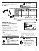
Страница 2: ...arted A Design Installation Location Considerations 5 B Thermostat Wall Control Location 6 C Tools And Supplies Needed 6 D Inspect Appliance and Components 6 E Install Checklist 7 3 Dimensions and Cle...

Страница 3: ...hour LHV Tested Efficiency 69 5 HHV Tested Efficiency 65 1 EPA BTU Output 7 500 to 36 600 per hr BTU Input 13 100 to 49 900 per hr Vent Size 3 or 4 Type L or PL Hopper Capacity 120 lbs Fuel Premium W...

Страница 4: ...composed of any combination of the following Steel Plaster Brick Iron Concrete Tile Glass Slate Materials reported as passing ASTM E 136 Standard Test Method for Behavior of Metals in a Vertical Tube...

Страница 5: ...ght requirement prior to installation The weight of the appliance is 240 lbs NOTICE Check building codes prior to installation Installation MUST comply with local regional state and national codes and...

Страница 6: ...the installation to ensure maximum safety and benefit Follow pipe manufacturer instructions for installation and air clearance requirements Risk of Fire Damaged parts could impair safe operation Do N...

Страница 7: ...ng this checklist for your file That this checklist remain visible at all times on the appliance until the installation is complete Electrical 120 VAC unswitched power provided to the appliance Check...

Страница 8: ...e Dimensions Figure 8 3 Front View Figure 8 1 Top View Figure 8 2 Side View 10 in 252mm 10 in 252mm 2 1 4 in 59mm 23 3 4 in 603mm 36 1 2 in 927mm 9 1 2 in 243mm 24 1 2 in 622mm 12 1 2 in 318mm 25 7 8...

Страница 9: ...nch Offset Adapter 811 0720 Figure 9 4 Side View w Top Vent Adapter TPVNT 5 3 to 4 inch Offset Adapter 811 0720 Figure 9 1 Top View w Top Vent Adapter TPVNT 5 12 1 4 in 311mm 12 1 4 in 311mm 2 7 8 in...

Страница 10: ...5 3 to 6 inch Offset Adapter 812 3570 12 1 4 in 311mm 12 1 4 in 311mm 4 1 8 in 103mm 4 1 8 in 103mm 28 1 8 in 714mm 28 1 8 in 714mm 30 1 8 in 765mm 30 1 8 in 765mm Figure 10 3 Top View w Top Vent Adap...

Страница 11: ...ter TPVNT 6 3 to 4 inch Offset Adapter 811 0720 Figure 11 2 Side View w Top Vent Adapter TPVNT 6 3 to 4 inch Offset Adapter 811 0720 9 7 8 in 252mm 9 7 8 in 252mm 3 1 8 in 80mm 3 1 8 in 80mm 15 1 8 in...

Страница 12: ...Back Wall to Adapter 1 25 E Side Wall to Appliance 14 356 F Back Wall to Appliance 6 1 4 159 Corner Installation Inches Millimeters G Walls to Appliance 2 51 Vertical Installation Inches Millimeters...

Страница 13: ...ach side of pipe shaded area to the wall thimble 152mm Front of glass 348mm USA INSTALLATIONS A non combustible floor protection is recommended extending beneath the flue pipe when installed with hori...

Страница 14: ...3 4 1441 n a n a B Width 53 1346 n a n a C Depth n a n a 48 1219 D To Side Wall 14 356 n a n a All minimums listed are to a combustible surface NOTE Illustrations reflect typical installations and ar...

Страница 15: ...rts of the structure P 12 in Clearance above roof line for vertical terminations All minimum clearances are listed with an Outside Air Kit OAK installed unless otherwise noted in table below 24 in Abo...

Страница 16: ...d may consume the air needed for the appliance It may be necessary to add additional ventilation to the space in which the pellet appliance is located Consult with your local HVAC professional to dete...

Страница 17: ...mney Install through the warm airspace enclosed by the building envelope This helps to produce more draft especially during lighting and die down of the fire Considerations for successful draft includ...

Страница 18: ...re 18 2 1 Locate the calculated equivalent feet of pipe on the vertical left side of the chart 2 Move to the right horizontally on the chart until you reach your altitude above sea level 3 If you fall...

Страница 19: ...best for your installation 2 in 51mm Minimum 2 in 51mm Minimum 6 in 152mm Minimum 6 in 152mm Minimum Figure 19 2 5 Venting Systems NOTE In Canada where passage through a wall or partition of combusti...

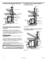
Страница 20: ...tructions for all reduced air clearances installations B Vertical into Existing Class A Chimney Firestop Flashing Rain Cap 6 in 152mm Minimum Non combustible Hearth Pad 3 in 76mm Minimum Cleanout Cove...

Страница 21: ...Flue Liner with Airspace Concrete Cap Non combustible Hearth Pad Airtight Clean Out Door Clean Out cover Sheathing 3 in 76mm Minimum 1 in 25mm Clearance Flashing Fireclay flue Liner with Airspace Con...

Страница 22: ...ation Cap Hose Clamp Trim Ring 2 inch flex hose Hose Clamp Collar Assembly Air Intake Channel Discard Figure 22 2 1 Measure distance from floor to air vent opening in appliance and mark location on wa...

Страница 23: ...ady in the short horizontal pipe in the top vent adapter as a guide Install the 2 screws Figure 23 1 6 Install the vent pipe into the top vent adapter 7 To clean the top vent adapter open the clean ou...

Страница 24: ...the thermostat from the mounting plate by gently pulling the two pieces apart c Slide thermostat wires through the back of the mounting plate Figure 24 3 d Connect your thermostat wire to the terminal...

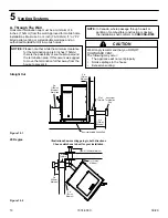
Страница 25: ...Cap Roof Flashing Storm Collar Joist Shield Firestop Double Wall Connector Pipe Figure 25 1 CAUTION THE STRUCTURAL INTEGRITY OF THE MOBILE HOME FLOOR WALL AND CEILING ROOF MUST BE MAINTAINED Do NOT cu...

Страница 26: ...26 09 20 7074 803C A Service Maintenance Log 8 Reference Materials Date of Service Performed By Description of Service...

Страница 27: ...27 09 20 7074 803C Date of Service Performed By Description of Service...

Страница 28: ...28 09 20 7074 803C Date of Service Performed By Description of Service...

Страница 29: ...29 09 20 7074 803C Date of Service Performed By Description of Service...

Страница 30: ...0 0810 Power Cord 812 1180 Y Thermostat Mechanical 812 3760 Y Touch Up Paint 3 42 19905 Fuse 7 Amp Junction Box Pkg of 10 812 0380 10 Y Hose Vacuum 5 32 Id 3 Ft SRV240 0450 Y Hose Barb Assembly SRV229...

Страница 31: ...ner Packs Rivnut Repair Kit RIVNUT REPAIR Y Bolt Hex Head 1 4 20 X 1 Pkg of 10 25221A 10 Y Guide Pin Sleeve Pkg of 25 31120 25 Y Hurricane Screw Pkg of 40 SRV2005 861 40 Nut 2 Wy Side Lock Jam 3 Pkg o...

Страница 32: ...maintenance instructions included Read understand and follow these instructions for safe installation and operation Leave this manual with party responsible for use and operation of this appliance We...

Отзывы: