


QSA Global, Inc.
40 North Avenue Burlington, MA 01803
888.272.2242
781.272.2000
qsa-global.com
Operations Manual
MAN-038 March 2019
Page 67 of 100
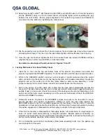
solvent into a used solvent container. Refill the source guide tube with clean solvent and repeat the
cleaning operation. Repeat this cleaning process until the solvent poured out of the source guide tube
into the used solvent container is clean. Use a compressed-air hose to blow out any residual solvent
from the source guide tubes. Use of a clean white cloth attached to one end of the source guide tube
will trap any debris or residual solvent when blowing out the source guide tubes. Repeat the cleaning
process until the cloth ‘trap’ indicates dirt is not present within the source guide tubes.
c.
Carefully inspect the entire length of each source guide tube for cuts and melted areas. Repairs to cut
or melted areas can be accomplished by taping the area with 3M™ yellow polyvinyl tape (or black
polyvinyl electrical tape). Taping the damaged area of the polyvinyl sheath will prevent the ingress of
water and other liquid that would cause corrosion to the remote control cable. Carefully look and feel
for dents and depressions in the source guide tubes. Even a small inward dent in the source guide
tube could cause a seized source assembly resulting in emergency operations. A ‘mock’ (Model
A424-13XL or A424-14XL) source assembly attached to a section of control cable that is pushed
through the entire length of source guide tube provides additional confirmation the source guide tube
suitable for use.
d. Inspect the swage fittings of each source guide tube to ensure the threads are not stripped or galled.
If the threads are damaged, the use of a 1inch-18 tap or die and oil can be used to clean the
damaged area. Using moderate pressure, attempt to twist the swage fitting off the source guide tube.
If any movement is possible, remove from service and replace the swage fitting. Inspect the source
guide tube near the swage fitting for breaks and bulging, remove from service and send to a service
center for repairs. Inspect the exposure head (source stop) for excessive wear or perforations on the
end-stop and the side where the collimator (beam limiter) is mounted. Damaged fittings or exposure
heads on source guide tubes can be replaced at a QSA Global service center. If the swage fittings
are not damaged and are securely attached to the source guide tube, apply a light coat of grease to
the threads and install the protective covers over the fittings.
e. Thoroughly clean the bayonets (86062-110 or 86062-330) in clean solvent and thoroughly dry. No
disassembly is required for servicing these swaged bayonet adaptors. Inspect the ears on the
bayonet fitting to ensure they are not bent, broken or excessively worn. Inspect the swivel bayonet
nut to ensure the threads are not stripped, clogged with material and that it rotates freely. Inspect the
bayonet to verify the separation gap is not excessively wide or loose. Verify the identification marking
(110 or 330) on the bayonet is legible for easy identification. After cleaning, screw the bayonet onto a
source guide tube to verify the threads of the bayonet nut properly engage to the threads of the
source guide tube. Test the bayonet on the outlet port of the gamma-ray source projector as
described in Section 4.3.3.e.
4.6.4
Misconnect Test After Reloading Sealed Source into the Gamma-ray source projector
After performing the annual maintenance, the complete radiography system must be tested by the
maintenance program administrator or Radiation Safety Officer. A misconnect test on the gamma-ray
source projector including the radioactive source assembly and wind-out controls effectively tests the
integrity of the entire locking system. This procedure detects long-term wear (or damage) of the
interrelated failsafe system including identification of any excess wear on the control cable connector,
device locking mechanism and sealed source connectors simultaneously.
Note: Component wear occurs to both the control assemblies and the device locking
mechanisms over time, therefore, to ensure acceptable equipment operation, the
misconnect test must be performed on each device lock assembly and control assembly
that will be used for radiographic operations. All remote controls must be tested using a
QSA Global, Inc. manufactured automatic securing mechanism equipped with a QSA
Global, Inc. manufactured source assembly, 550 jumper or a mock source assembly
(A424-14XL for the SENTINEL
SENTRY 110 and A424-13XL for the SENTRY 330) to ensure
the effectiveness of the misconnect test.


