


QSA Global, Inc.
40 North Avenue Burlington, MA 01803
888.272.2242
781.272.2000
qsa-global.com
Operations Manual
MAN-038 March 2019
Page 34 of 100
3.6.1 Remote Control Inspection
:
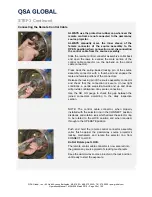
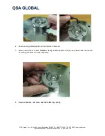
a. Uncoil the remote controls at the site. Inspect the control crank to assure all fastening hardware are
present and tightened and that the crank handle is properly secured. If the control crank is equipped
with an odometer, zero the odometer while the control cable is fully retracted. Verify the odometer, if
equipped, is fully functional.
b. Ensure the instructions on the control crank's label are legible. These instructions are important to
safety, especially when assistants are being trained or during an emergency. Without the written
instructions, it’s conceivable that a radiographer could become confused as to which direction the
crank handle must be rotated to retract or expose the source assembly.
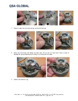
c. Ensure the lever brake is operational if equipped. Resistance should be felt while rotating the crank
handle with the brake in the ON position. If the extreme controls are being used, set the brake
plunger knob to the ON position (engaged into one the drive gear cover plate indents) and attempt to
turn the handle using moderate pressure to ensure security. Then, test the brake plunger to ensure
that it disengages easily before use. Inspect the remote control conduit fittings to verify they are
secured to the control crank. This can be accomplished by trying to rotate the nut that mounts to the
control crank assembly.
3.6.2 Remote Control Conduit Inspection
:
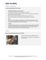
a. Inspect the control conduit where it is swaged onto the fittings that mount on the control crank. There
should be no evidence of cracks or breaks in the waterproof sheath. Also, look for bulges in that area
that result from repeated flexing.
b. Visually inspect the entire length of both control conduits looking for dents, cuts and thermally
damaged areas. During this inspection, the radiographer should use his hands to feel for inward
dents. Cuts and melted areas found on the control conduits should be sealed with PVC tape to
prevent against the ingress of water.
c. Inspect the control conduits where they are swaged to the swage fittings that are mounted to the
connecting plug assembly. There should be no evidence of cracks, breaks or bulges in the waterproof
sheath.
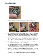
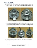
d. Remove the protective cover from the connecting plug assembly. Inspect the connecting plug
assembly to verify the movable jaws are not excessively loose and the connecting collar pins are not
excessively loose, have rotated or are bent. Check the control sheath swage fittings to verify they are
not loose where they are joined to the connecting plug assembly.
3.6.3 Remote Control Drive Cable Inspection
:
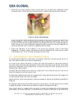
a. Inspect the control cable connector as it protrudes out of the connecting plug assembly. The control
cable connector should not be bent or at an angle exceeding 15 degrees relative to the control cable
centerline. If a control cable connector is repeatedly bent at an angle greater than 15 degrees,
damage to the control cable may be introduced by straightening the bend.
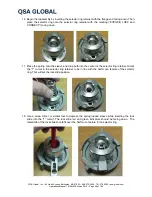
Inspect the control cable (male) connector to verify the shank and the ball of the connector are not
bent or cracked.
Using moderate hand pressure, attempt to twist the control cable connector from the control cable. If
the control cable connector can be twisted (moved) using hand pressure or appears bent or cracked,
remove from service and label as defective.


