SVS-VISTEK
Feature-Set
74
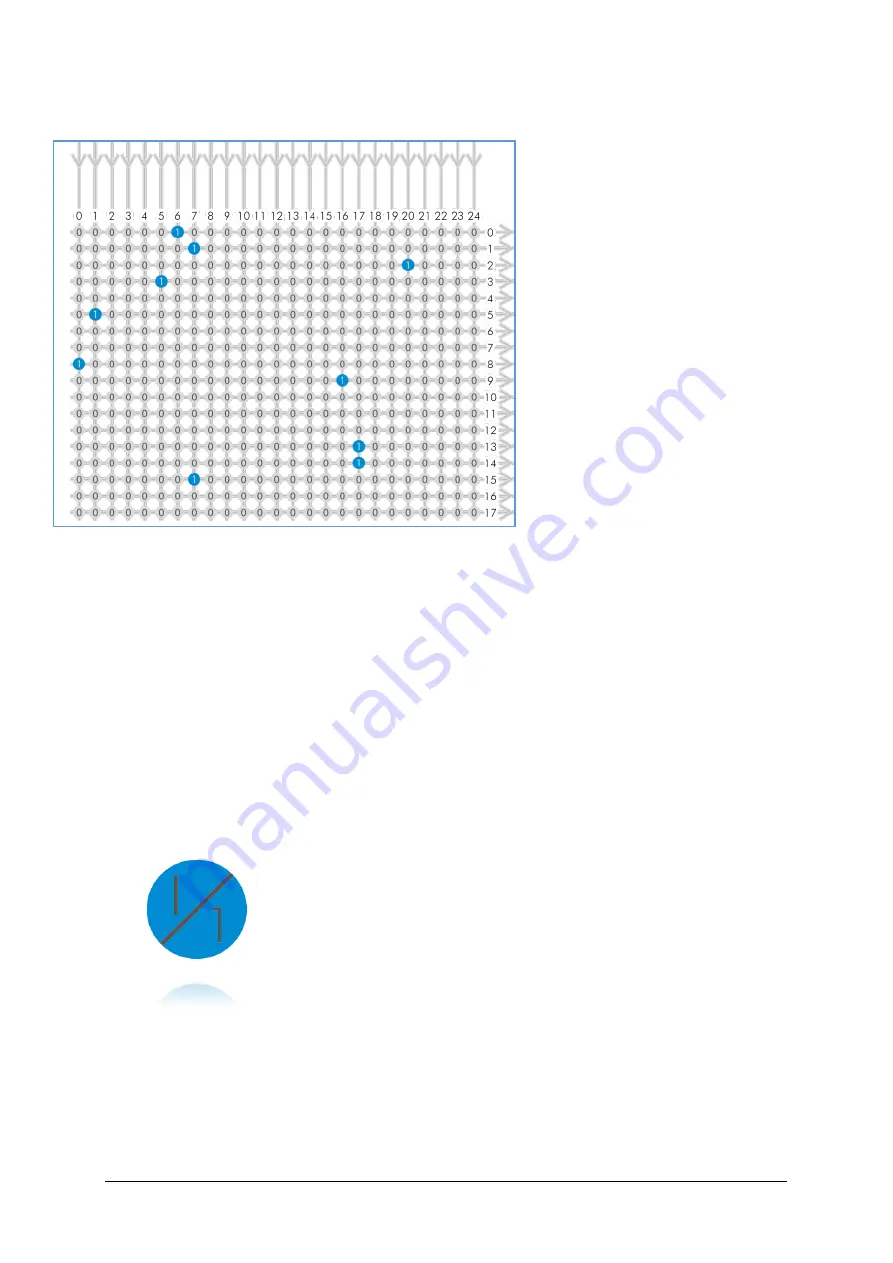
Example of an IOMUX configuration
>
The trigger signal comes in on
line 0
>
Debounce it.
connect line 0 to 8:
1000000000000000000000000
signal appears again on line 15 –
debouncer out
>
Use the prescaler to act only on
every second pulse.
connect line 16 to 9.
0000000000000000100000000
signal appears again on line 17 –
debouncer out
>
Configure a strobe illumination
with pulseloop module 0
connect line 17 to 13
signal from pulse loop module 0
appears on line 6
connect line 6 to 0 (output 0)
>
Set an exposure signal with
pulseloop module 1.
connect line 17 to 6
>
Tell another component that the camera is exposing the sensor.
connect line 17 to 14
signal from pulse loop module 1 appears on line 7
connect line 7 to 1 (output 1)
>
Turn of a light that was ON during the time between two pictures.
connect line 17 to 15
invert signal from pulse loop module 2
it appears on line 20
connect line 20 to 2 (output 2)
Inverter
&
Set-to-1
Inverter and “set to 1” is part of every input and every output of the
modules included in the IOMUX.
I
N V E R T E R
The inverter enabled at a certain line provides the reverse signal to or
from a module.
S
E T T O
“ 1 ”
With set to “1” enabled in a certain line, this line will provide a high
signal no matter what signal was connected to the line before.
S
E T T O
“ 1 ”
–
I N V E R S
The inverse of a set to “1” line will occour as a low signal, regardle the
actual signal that came to the inverter modul.
Содержание EXO Series
Страница 5: ...Contents v 11 IP protection classes 125 12 Glossary of Terms 126 13 Index of figures 129 14 Index 132 ...
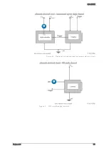
Страница 18: ...SVS VISTEK Getting Started 18 4 6 Driver Circuit Schematics Figure 4 basic Illustration of driver circuit ...
Страница 21: ...SVS VISTEK Connectors 21 ...
Страница 26: ...SVS VISTEK Dimensions 26 Side Right Top ...
Страница 27: ...SVS VISTEK Dimensions 27 Bottom Back ...
Страница 28: ...SVS VISTEK Dimensions 28 Cross Section 6 2 exo250 CL exo252 CL front side Left ...
Страница 29: ...SVS VISTEK Dimensions 29 ...
Страница 30: ...SVS VISTEK Dimensions 30 Side Right Top ...
Страница 31: ...SVS VISTEK Dimensions 31 Bottom Back Cross Section ...
Страница 32: ...SVS VISTEK Dimensions 32 6 3 exo267 CL exo304 CL ...
Страница 33: ...SVS VISTEK Dimensions 33 ...
Страница 34: ...SVS VISTEK Dimensions 34 ...
Страница 35: ...SVS VISTEK Dimensions 35 6 4 exo4000 CL front side Left ...
Страница 36: ...SVS VISTEK Dimensions 36 Side Right Top ...
Страница 37: ...SVS VISTEK Dimensions 37 Bottom Back ...
Страница 38: ...SVS VISTEK Dimensions 38 Cross Section ...
Страница 39: ...SVS VISTEK Dimensions 39 6 5 exo5000 U3 front side Left ...
Страница 40: ...SVS VISTEK Dimensions 40 Side Right Top ...
Страница 41: ...SVS VISTEK Dimensions 41 Bottom Back Cross Section ...
Страница 65: ...SVS VISTEK Feature Set 65 ...
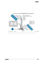
Страница 71: ...SVS VISTEK Feature Set 71 Figure 42 I O Lines with open end indicate physical in and outputs ...
Страница 81: ...SVS VISTEK Feature Set 81 Strobe Control Example Setup Figure 47 Illustration of an application using the 4IO ...
Страница 102: ...SVS VISTEK Specifications 102 Spectral sensitivity characteristics Figure 64 IMX183LQJ Figure 65 IMX183LLR Color Mono ...
Страница 105: ...SVS VISTEK Specifications 105 Spectral sensitivity characteristics Figure 66 IMX249LQJ Figure 67 IMX249LLJ Color Mono ...
Страница 108: ...SVS VISTEK Specifications 108 Spectral sensitivity characteristics Figure 68 IMX250LQJR Figure 69 IMX250LLR Color Mono ...
Страница 111: ...SVS VISTEK Specifications 111 Spectral sensitivity characteristics Figure 70 IMX267LQR Figure 71 IMX267LLR Color Mono ...
Страница 114: ...SVS VISTEK Specifications 114 Spectral sensitivity characteristics Figure 72 IMX304LQR Figure 73 IMX304LLR Color Mono ...
Страница 124: ...SVS VISTEK Troubleshooting 124 Space for further descriptions screenshots and log files ...
Страница 135: ...SVS VISTEK Index 135 Vertical Binning 59 Viewer Software 14 Warranty 121 WARRANTY 7 121 White Balance 54 Why PWM 84 ...

