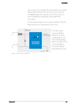
SVS-VISTEK
Feature-Set
88
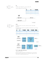
OR
If neither input is high, a low pulse_out (0) results.
Combine trigger input one and two.
A
B
Y = A v B
0
0
0
0
1
1
1
0
1
1
1
1
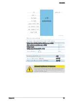
NOR
No trigger input – one nor two – results in a high or a low level
pulse_out.
Invert both trigger inputs. By inverting the resulting pulse_out you will get
the NOR I pulse
A
B
Y = A
⊽
B
NOR
Y = A
∨
B
NOR i
0
0
1
0
0
1
0
1
1
0
0
1
1
1
0
1
7.3.7
Serial data interfaces
(ANSI EIA/) TIA-232-F
RS-232 and RS-422 (from EIA, read as Radio Sector or commonly as
Recommended Standard) are technical standards to specify electrical
characteristics of digital signaling circuits.
Содержание EXO Series
Страница 5: ...Contents v 11 IP protection classes 125 12 Glossary of Terms 126 13 Index of figures 129 14 Index 132 ...
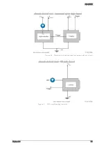
Страница 18: ...SVS VISTEK Getting Started 18 4 6 Driver Circuit Schematics Figure 4 basic Illustration of driver circuit ...
Страница 21: ...SVS VISTEK Connectors 21 ...
Страница 26: ...SVS VISTEK Dimensions 26 Side Right Top ...
Страница 27: ...SVS VISTEK Dimensions 27 Bottom Back ...
Страница 28: ...SVS VISTEK Dimensions 28 Cross Section 6 2 exo250 CL exo252 CL front side Left ...
Страница 29: ...SVS VISTEK Dimensions 29 ...
Страница 30: ...SVS VISTEK Dimensions 30 Side Right Top ...
Страница 31: ...SVS VISTEK Dimensions 31 Bottom Back Cross Section ...
Страница 32: ...SVS VISTEK Dimensions 32 6 3 exo267 CL exo304 CL ...
Страница 33: ...SVS VISTEK Dimensions 33 ...
Страница 34: ...SVS VISTEK Dimensions 34 ...
Страница 35: ...SVS VISTEK Dimensions 35 6 4 exo4000 CL front side Left ...
Страница 36: ...SVS VISTEK Dimensions 36 Side Right Top ...
Страница 37: ...SVS VISTEK Dimensions 37 Bottom Back ...
Страница 38: ...SVS VISTEK Dimensions 38 Cross Section ...
Страница 39: ...SVS VISTEK Dimensions 39 6 5 exo5000 U3 front side Left ...
Страница 40: ...SVS VISTEK Dimensions 40 Side Right Top ...
Страница 41: ...SVS VISTEK Dimensions 41 Bottom Back Cross Section ...
Страница 65: ...SVS VISTEK Feature Set 65 ...
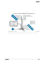
Страница 71: ...SVS VISTEK Feature Set 71 Figure 42 I O Lines with open end indicate physical in and outputs ...
Страница 81: ...SVS VISTEK Feature Set 81 Strobe Control Example Setup Figure 47 Illustration of an application using the 4IO ...
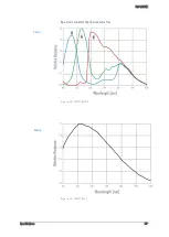
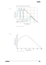
Страница 102: ...SVS VISTEK Specifications 102 Spectral sensitivity characteristics Figure 64 IMX183LQJ Figure 65 IMX183LLR Color Mono ...
Страница 105: ...SVS VISTEK Specifications 105 Spectral sensitivity characteristics Figure 66 IMX249LQJ Figure 67 IMX249LLJ Color Mono ...
Страница 108: ...SVS VISTEK Specifications 108 Spectral sensitivity characteristics Figure 68 IMX250LQJR Figure 69 IMX250LLR Color Mono ...
Страница 111: ...SVS VISTEK Specifications 111 Spectral sensitivity characteristics Figure 70 IMX267LQR Figure 71 IMX267LLR Color Mono ...
Страница 114: ...SVS VISTEK Specifications 114 Spectral sensitivity characteristics Figure 72 IMX304LQR Figure 73 IMX304LLR Color Mono ...
Страница 124: ...SVS VISTEK Troubleshooting 124 Space for further descriptions screenshots and log files ...
Страница 135: ...SVS VISTEK Index 135 Vertical Binning 59 Viewer Software 14 Warranty 121 WARRANTY 7 121 White Balance 54 Why PWM 84 ...


