SVS-VISTEK
Feature-Set
68
7.2.5
ROI
/
AOI
In Partial Scan or Area-Of-Interest or Region-Of-Interest (ROI) -mode only
a certain region will be read.
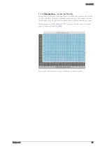
Figure 39: AOI on a CCD sensor
Selecting an AOI will reduce the number of horizontal lines being read.
This will reduce the amount of data to be transferred, thus increasing the
maximum speed in term of frames per second.
With CCD sensors, setting an AOI on the left or right side does not affect
the frame rate, as lines must be read out completely.
In CMOS Sensors, AOI can be chosen, too.
7.3
I/O Features
7.3.1
Assigning I/O Lines – IOMUX
The IOMUX is best described as a switch matrix. It connects inputs, and
outputs with the various functions of SVCam I/O. It also allows combining
inputs with Boolean arguments.
Figure 40: "IN0" connected to "debouncer"
LineSelector
translation
Содержание EXO Series
Страница 5: ...Contents v 11 IP protection classes 125 12 Glossary of Terms 126 13 Index of figures 129 14 Index 132 ...
Страница 18: ...SVS VISTEK Getting Started 18 4 6 Driver Circuit Schematics Figure 4 basic Illustration of driver circuit ...
Страница 21: ...SVS VISTEK Connectors 21 ...
Страница 26: ...SVS VISTEK Dimensions 26 Side Right Top ...
Страница 27: ...SVS VISTEK Dimensions 27 Bottom Back ...
Страница 28: ...SVS VISTEK Dimensions 28 Cross Section 6 2 exo250 CL exo252 CL front side Left ...
Страница 29: ...SVS VISTEK Dimensions 29 ...
Страница 30: ...SVS VISTEK Dimensions 30 Side Right Top ...
Страница 31: ...SVS VISTEK Dimensions 31 Bottom Back Cross Section ...
Страница 32: ...SVS VISTEK Dimensions 32 6 3 exo267 CL exo304 CL ...
Страница 33: ...SVS VISTEK Dimensions 33 ...
Страница 34: ...SVS VISTEK Dimensions 34 ...
Страница 35: ...SVS VISTEK Dimensions 35 6 4 exo4000 CL front side Left ...
Страница 36: ...SVS VISTEK Dimensions 36 Side Right Top ...
Страница 37: ...SVS VISTEK Dimensions 37 Bottom Back ...
Страница 38: ...SVS VISTEK Dimensions 38 Cross Section ...
Страница 39: ...SVS VISTEK Dimensions 39 6 5 exo5000 U3 front side Left ...
Страница 40: ...SVS VISTEK Dimensions 40 Side Right Top ...
Страница 41: ...SVS VISTEK Dimensions 41 Bottom Back Cross Section ...
Страница 65: ...SVS VISTEK Feature Set 65 ...
Страница 71: ...SVS VISTEK Feature Set 71 Figure 42 I O Lines with open end indicate physical in and outputs ...
Страница 81: ...SVS VISTEK Feature Set 81 Strobe Control Example Setup Figure 47 Illustration of an application using the 4IO ...
Страница 102: ...SVS VISTEK Specifications 102 Spectral sensitivity characteristics Figure 64 IMX183LQJ Figure 65 IMX183LLR Color Mono ...
Страница 105: ...SVS VISTEK Specifications 105 Spectral sensitivity characteristics Figure 66 IMX249LQJ Figure 67 IMX249LLJ Color Mono ...
Страница 108: ...SVS VISTEK Specifications 108 Spectral sensitivity characteristics Figure 68 IMX250LQJR Figure 69 IMX250LLR Color Mono ...
Страница 111: ...SVS VISTEK Specifications 111 Spectral sensitivity characteristics Figure 70 IMX267LQR Figure 71 IMX267LLR Color Mono ...
Страница 114: ...SVS VISTEK Specifications 114 Spectral sensitivity characteristics Figure 72 IMX304LQR Figure 73 IMX304LLR Color Mono ...
Страница 124: ...SVS VISTEK Troubleshooting 124 Space for further descriptions screenshots and log files ...
Страница 135: ...SVS VISTEK Index 135 Vertical Binning 59 Viewer Software 14 Warranty 121 WARRANTY 7 121 White Balance 54 Why PWM 84 ...


