SVS-VISTEK
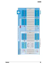
Connectors
22
5.1.3
Camera Link timing
It might be interesting to know when “valid data” can be expected exactly.
px
h
= pixel horizontal [count]
px
v
= pixel vertical [count]
LVAL – t
L v d
Every line has periods with no valid data. The Duration of None Valid
Data between two lines (
t
nvd
) is three time the Camera Link clock (clk).
Delay before every first line is 2 times clk.
𝑡
𝐿𝐿𝐿
=
𝑝𝑝
ℎ
𝐶𝐶
_
𝑔𝑔𝑔𝑔𝑔𝑡𝑔𝑔
_
𝑋
×
1
𝐶𝐶
_
𝑐𝑐𝑔𝑐𝑐
CL_clock = 85 MHz
FVAL – t
F v d
Frames are not sent permanently. Between two frames will be a gap –
even at highest frame rates. Minimum duration between two valid frame
signals is the duration of one line.
𝑡
𝐹𝐿𝐿
= 2 ×
1
𝐶𝐶
_
𝑐𝑐𝑔𝑐𝑐
+ (
𝑡
𝐿𝐿𝐿
+
𝑡
𝑛𝐿𝐿
) ×
𝑝𝑝
𝐿
𝐶𝐶
_
𝑔𝑔𝑔𝑔𝑔𝑡𝑔𝑔
_
𝑌
Содержание EXO Series
Страница 5: ...Contents v 11 IP protection classes 125 12 Glossary of Terms 126 13 Index of figures 129 14 Index 132 ...
Страница 18: ...SVS VISTEK Getting Started 18 4 6 Driver Circuit Schematics Figure 4 basic Illustration of driver circuit ...
Страница 21: ...SVS VISTEK Connectors 21 ...
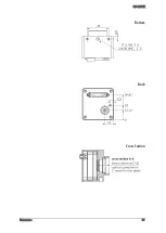
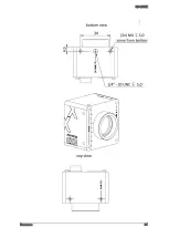
Страница 26: ...SVS VISTEK Dimensions 26 Side Right Top ...
Страница 27: ...SVS VISTEK Dimensions 27 Bottom Back ...
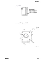
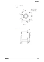
Страница 28: ...SVS VISTEK Dimensions 28 Cross Section 6 2 exo250 CL exo252 CL front side Left ...
Страница 29: ...SVS VISTEK Dimensions 29 ...
Страница 30: ...SVS VISTEK Dimensions 30 Side Right Top ...
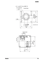
Страница 31: ...SVS VISTEK Dimensions 31 Bottom Back Cross Section ...
Страница 32: ...SVS VISTEK Dimensions 32 6 3 exo267 CL exo304 CL ...
Страница 33: ...SVS VISTEK Dimensions 33 ...
Страница 34: ...SVS VISTEK Dimensions 34 ...
Страница 35: ...SVS VISTEK Dimensions 35 6 4 exo4000 CL front side Left ...
Страница 36: ...SVS VISTEK Dimensions 36 Side Right Top ...
Страница 37: ...SVS VISTEK Dimensions 37 Bottom Back ...
Страница 38: ...SVS VISTEK Dimensions 38 Cross Section ...
Страница 39: ...SVS VISTEK Dimensions 39 6 5 exo5000 U3 front side Left ...
Страница 40: ...SVS VISTEK Dimensions 40 Side Right Top ...
Страница 41: ...SVS VISTEK Dimensions 41 Bottom Back Cross Section ...
Страница 65: ...SVS VISTEK Feature Set 65 ...
Страница 71: ...SVS VISTEK Feature Set 71 Figure 42 I O Lines with open end indicate physical in and outputs ...
Страница 81: ...SVS VISTEK Feature Set 81 Strobe Control Example Setup Figure 47 Illustration of an application using the 4IO ...
Страница 102: ...SVS VISTEK Specifications 102 Spectral sensitivity characteristics Figure 64 IMX183LQJ Figure 65 IMX183LLR Color Mono ...
Страница 105: ...SVS VISTEK Specifications 105 Spectral sensitivity characteristics Figure 66 IMX249LQJ Figure 67 IMX249LLJ Color Mono ...
Страница 108: ...SVS VISTEK Specifications 108 Spectral sensitivity characteristics Figure 68 IMX250LQJR Figure 69 IMX250LLR Color Mono ...
Страница 111: ...SVS VISTEK Specifications 111 Spectral sensitivity characteristics Figure 70 IMX267LQR Figure 71 IMX267LLR Color Mono ...
Страница 114: ...SVS VISTEK Specifications 114 Spectral sensitivity characteristics Figure 72 IMX304LQR Figure 73 IMX304LLR Color Mono ...
Страница 124: ...SVS VISTEK Troubleshooting 124 Space for further descriptions screenshots and log files ...
Страница 135: ...SVS VISTEK Index 135 Vertical Binning 59 Viewer Software 14 Warranty 121 WARRANTY 7 121 White Balance 54 Why PWM 84 ...


