background image

Introduction .................................................................................................................

...

..........................................................3

Parts Ordering / Customer Service. . ...........................................................................................................................3

Safety Rules . ......................................................................................................................................................................... 4

Safety Symbols . .......................................................................................................................................................... 4

Safety Instructions . .................................................................................................................................................... 4

Features .................................................................................................................................................................................. 7

Control Panel Functions . . .................................................................................................................................................... 8

Fuel 

Selector Switch

.................................................................................................................................................... 8

Indicator Lights. . ......................................................................................................................................................... 8

A

C Circuit Breaker..................................................................................................................................................... 

10

Engine  “Economy”


Control


.


.


....................................................................................................................................

 10

Parallel Connections........................................ .................................................................................................... 10

Ground  Terminal. . ..................................................................................................................................................... 10

Assembly . ....................................................................................................................................................................

.

.

.

...... 11

Connecting  Generator  to  a Building  Electrical  System............................................................................................11

Adding Fuel. .............................................................................................................................................................. 11 

Checking/Adding Oil ................................................................................................................................................. 12

Operation . ............................................................................................................................................................................ 13

How to Start Engine. ................................................................................................................................................. 13

How to Stop Engine. .................................................................................................................................................. 14

Attaching Electrical Devices. .....................................................................................................................................1

5

Charging a 12 Volt Battery. ....................................................................................................................................... 15

AC  Parallel  Operation. ............................................................................................................................................. 16

Do Not Overload  Generator. .................................................................................................................................... 17

Wattage Reference Guide. ........................................................................................................................................ 17

Maintenance . ....................................................................................................................................................................... 18

Maintenance Schedule . . .......................................................................................................................................... 18

Checking Spark Plug    . . .......................................................................................................................................... 19

Changing Oil . ........................................................................................................................................................... 20

How to Clean Air Filter. ............................................................................................................................................. 21

How to Clean Fuel Filter . ....................................................................................................................................... 22

............................................................................................................................................................... 22

Troubleshooting .................................................................................................................................................................. 24

TABLE OF CONTENTS

Transport & Storage

USB Power Outlet....................................................................................................................................................... 8

Checking Muffler and Spark Arrestor . ..................................................................................................................... 21

Wiring Diagram...................................................................................................................................................................

... 25

CO Sensor...................

.................................. ..................................................................................................


.. 

9

Содержание PG4500BiSRCO

Страница 1: ...com Inverter Generator Gasoline OPERATOR S MANUAL Model PG4500BiSRCO Warning The Engine Exhaust from this product contains chemicals known to the State of California to cause cancer birth defects or other reproductive harm TM ...

Страница 2: ...l System 11 Adding Fuel 11 Checking Adding Oil 12 Operation 13 How to Start Engine 13 How to Stop Engine 14 Attaching Electrical Devices 15 Charging a 12 Volt Battery 15 AC Parallel Operation 16 Do Not Overload Generator 17 Wattage Reference Guide 17 Maintenance 18 Maintenance Schedule 18 Checking Spark Plug 19 Changing Oil 20 How to Clean Air Filter 21 How to Clean Fuel Filter 22 22 Troubleshooti...

Страница 3: ...oducts Inc When operating and maintaining this product as instructed in this manual your generator will give you many years of reliable service Product Specifications This generator is an engine driven revolving field alternating current AC portable generator It is designed to supply electrical power to operate tools appliances camping equipment lighting or serve as a backup power source during po...

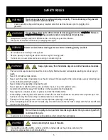
Страница 4: ...te indoors or in a confined space that prevents dangerous carbon monoxide gas from dissipating Using a generator indoors CAN KILL YOU IN MINUTES Carbon monoxide gas is a poisonous odorless gas that can cause headache confusion fatigue nausea fainting sickness seizures or death If you start to experience any of these symptoms IMMEDIATELY get fresh air and seek medical attention Never use indoors in...

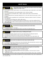
Страница 5: ...lammable debris When adding or draining fuel unit should be turned off for at least 2 minutes to cool before removing fuel cap If unit has been running the fuel cap may be under pressure removeslowly Tokeep fuel from spilling secure unit so it cannot tip while operating or transporting When transporting unit disconnect the spark plug wire and make sure the fuel tank is empty with the fuel shutoff ...

Страница 6: ... Only when operating at the preset governed speed this generator will supply the correct rated frequency and voltage WARNING Generator must be properly grounded to prevent electrocution Only operate generator on a level surface If connected to a structure connect the ground terminal on the frame to an appropriate ground WARNING This generator produces high voltage which could result in burnsor ele...

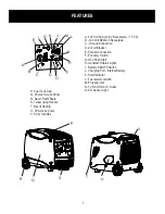
Страница 7: ...Generator Status Lights I Battery ON OFF Switch J Charging Port Internal Battery K Start Indicator L Fuel selector switch M Propane inlet N 5V DC USB 2 1A Outlet O CO Sensor Light V Q P R U S P Fuel Tank Cap Q Engine Service Panel R Never Flat Wheels S Telescoping Handle T Recoil Handle U Oil Access Cover V Carry Handles T J L H F D C B A FEATURES 7 E I G K M N O ...

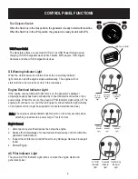
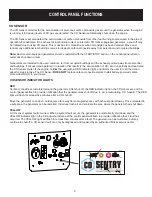
Страница 8: ...un but the red Engine Overload Indicator Light will stay on and power will no longer be supplied to connected electrical devices Note The engine overload indicator light may turn on for a few seconds when attaching a load due to a power surge This is normal USB Power Outlet Oil Warning Indicator light Overload Indicator light AC Pilot Indicator light Fuel Selector Switch When the Switch is in the ...

Страница 9: ...ea the CO Sensor shuts off the engine notifies the user with a RED indicator light and directs the user to read the Action Label for steps to take The CO Sensor DOES NOT replace carbon monoxide alarms Install battery powered carbon monoxide alarm s in your home CO SENSOR INDICATOR LIGHTS RED Carbon monoxide accumulated around the generator After shut off the RED indicator light in the CO Sensor ar...

Страница 10: ...n a nominal speed of of 3 100 r min AC Circuit Breaker When the AC Circuit Breaker is in the I position the generator is able to supply power to connected electrical devices When the AC Circuit Breaker shifts to the O position the generator will no longer supply power The AC Circuit Breaker automatically shifts to the O position when connecting electrical devices to the generator that exceed the g...

Страница 11: ... isolated from the utility power source The connection must comply with all local electrical codes and applicablelaws Set generator outdoors in a well ventilated area away from structures and people Slowly remove fuel cap Insert a funnel into the fuel tank and carefully pour gasoline into the tank until fuel level reaches 1 inches below the top of the neck Be careful not to overfill the tank to al...

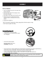
Страница 12: ... crankcase dipstick Recommended Oil SAE 10W 30 Oil Capacity 0 6L 20 2oz Checking Adding Engine Oil Generator has been shipped without engine oil You must add engine oil before operating this generator Always check oil level before each operation Battery Installation 1 Loosen four Phillips screws but do not remove them from the side panel 2 Carefully lift all four edges of the side panel releas the...

Страница 13: ...ere is gas in the tank thenTurn fuel selector knob to GASOLINE FOR LPG Make sure the LPG hose is safely secured from the generator to the tank then turn fuel selector knob to PROPANE fully open the valve on the propane tank OFF ON Turn battery switch ON Choose starting method as below For manual start Pull the recoil starter grip slowly until resistance is felt retract then pull rapidly For Push B...

Страница 14: ... for about 10 seconds Wait for the start light on the control panel to flash green Within 3 seconds press any button on the remote FOB for about 1 second and release Make sure the green light has stopped flashing to indicate successful pairing How to pair the remote FOB Disconnect all electrical loads from generator If ambient temperature is below 32ºF 0ºC allow about 3 minutes for the engine to w...

Страница 15: ...ator Start engine If the attached electrical load is small move the Economy switch to the ON position For a larger electrical load or if attaching multiple electrical devices move the Economy switch to the OFF position Make sure the green AC pilot indicator light is on When engine has stabilized plug in and switch on first load It is strongly recommended to plug in devices with the largest electri...

Страница 16: ...ext electrical load OPERATION WARNING A faulty appliance or power cord can create an electric shock Do not use electrical devices that have a damaged cord or plug If an appliance begins to operate abnormally becomes sluggish or stalls switch off and disconnect appliance immediately The appliance may have a fault or its rated load requirements exceeds the capacity of the generator To avoid damage t...

Страница 17: ...tor 800 800 Laser Printer 250 950 Copy Machine 700 800 Power Tools 1000W Quartz Halogen Work Light 1000 1000 Airless Sprayer HP 600 800 Reciprocating Saw 750 950 Circular Saw 7 1400 2300 Miter Saw 10 800 1200 Table Radial ArmSaw 1000 2000 Electric Drill HP 5 4 Amps 600 900 Hammer Drill 700 1000 Air Compressor 1600 4500 Other Home Security System 500 500 Garage Door Opener HP 750 750 Essentials Rat...

Страница 18: ...evel Make sure the air filter is clean Remove any debris that has collected on the generator and around the muffler and controls Use a vacuum cleaner to pick up loose debris If dirt is caked on use a soft bristlebrush Inspect the work area for hazards After Each Use Switch Off the battery Wait for the generator to become cool to the touch Store unit in a clean and dry area Maintenance Schedule Aft...

Страница 19: ...ype Spark plug should be replaced annually regardless of apparent condition Reconnect spark plug wire firmly until it clicks into place Standard Spark Plug F7TC F7RTC Spark Plug Gap 0 6 0 7mm 0 024 0 028 in Spark Plug Torque 20 0Nm 15 ft lb MAINTENANCE Carburetor Adjustment The carburetor is low emission and is equipped with a non adjustable idle mixture valve If adjustment is needed contact an au...

Страница 20: ... will meet each emission standard throughout its useful life Even with carburetor modification engine horsepower will decrease about 3 5 for each 1 000 foot 300 meter increase in altitude The effect of altitude on engine power will be greater than this if no carburetor modification is made Run the generator until the engine is warm then shutOFF Place generator on a firm and level surface raised on...

Страница 21: ...xcessive engine wear may result Allow hot components to cool before touching WARNING Avoid contacting hot areas of this generator 4 6 Order of removal Inspect muffler for cracks corrosion or other damage Remove screws then remove the muffler cover as shown Remove the cover then remove muffler cap muffler screen and spark arrester Check the muffler screen and spark arrester for carbon deposits Remo...

Страница 22: ...ator once every 7days For intermediate term storage from 3 6 months add fuel stabilizer to prevent stale fuel from causing acid and gum deposits in the fuel system and carburetor For long term storage drain the fuel charge the battery per 6 months Store a sheltered location such as a garage or outdoor storage shed where temperatures do not fall below freezing The generator must be Shipped Operated...

Страница 23: ...cause serious burns or fires Let the engine cool before transporting or storing the generator generator CAUTION Take care not to drop or strike the generator when transporting Do not place heavy objects on the Engine Long Term Storage Turn OFF the engine move the battery switch to OFF remove the fuel cap and the debris screen underneath the fuel cap Empty the fuel tank using a siphon and an approv...

Страница 24: ...lter 4 Stale fuel 5 Spark plug wire disconnected from spark plug 6 Bad spark plug 7 Water in fuel 8 Low oil level 9 Intake valve stuck open or close 10 Loss of enginecompression 11 Engine has flooded 12 CO Sensor indicator light turn red 13 CO Sensor indicator light turn yellow 1 Turn switch to ON 2 Replace Air filter 3 Clean or replace fuel filter 4 Replace fuel 5 Reconnect spark plug wire 6 Repl...

Страница 25: ...WIRING DIAGRAM 25 M θ θ ...

Отзывы: