background image

www.pulsar.pl   


INTRW  


16 

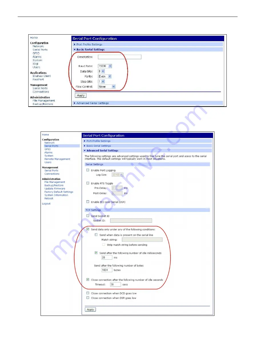
Setting the parameters of the serial port. 

Select the ‘Basic Serial Settings’ tab at the bottom of the page and adjust the settings as shown in the 

window below:  


Fig. 17. Setting the parameters of the serial port communication. 


Approve  the  settings  by  clicking  ‘Apply’.  Next,  select  the  ‘Advanced  Serial  Settings’  tab  at  the  bottom  and  make 
adjustments  in  the  ‘TCP  Setting’  section  accordingly  to  the  picture  below.  Approve  the  changes  with  the  ‘Apply’ 
button.  


Fig. 18. Configuration of communication parameters of the serial port. – the ‘TCP Settings’ tab. 

 
Reset the RS485-WiFi interface by pressing the ‘RST’ button on the module or by cutting off the power for 

a few seconds. After the reset, the connection between the interface and the router should be re-established after 
approx. 30s.  

Содержание INTRW

Страница 1: ...Interface RS485 WiFi v 1 0 CODE INTRW EN Edition 1st 6th Jan 2013 ...

Страница 2: ...he communication mode 13 4 6 1 Communication in LAN WAN 13 TCP Sockets profile settings 15 Setting the serial port 16 Settings in the PowerSecurity program 17 4 6 2 Communication in the WLAN serial bridge mode 19 Settings of the Serial Bridge profile Client Server 19 Setting the parameters of the serial port 19 Settings in the PowerSecurity program 20 5 Setting the communication parameters of the ...

Страница 3: ...us and the Ethernet network and dedicated for working with power supply units of the PSBEN Black Power group connected to WLAN WAN network To work correctly the device requires external power supply within the range of 10 30V DC e g drawn from a PSU of the PSBEN series The device is mounted in a hermetic enclosure that protects it against adverse environmental conditions The range of transmission ...

Страница 4: ...of devices A to A B to B Use a twisted pair cable as a transmission wire of the bus The bus shall be of a point to point topology the star type of topology is to be avoided If the bus wires are of a significant length it is recommended to use a shielded cable that will prevent from errors during communication and lowers the susceptibility to noise and emission of radio frequency interference It is...

Страница 5: ...www pulsar pl INTRW 5 Fig 2 The view of the interface with a description of the wires ...

Страница 6: ...ns between the interface and a PC that enables performing the configuration A newly purchased Wi Fi interface is delivered with basic configuration factory settings which is not adjusted to correct operation in the system As the communication with the interface is via radio waves it is important to adjust your router accordingly so that it can establish connection with the interface The most conve...

Страница 7: ... the power supply and then switch it back on If these actions prove insufficient begin the procedure of restoring the router s and the interface s factory settings once again 4 4 STEP 2 Configuration of the IP address To ensure a proper progress of the IP address changing procedure it is recommended to turn off the firewall of the anti virus program for the time of configuration process If the yel...

Страница 8: ...he Save button to approve the changes The Digi Device Discovery application will display a message about a required interface restart which shall be approved by clicking the OK button Next the window of device s resetting progress will appear 4 5 STEP 3 Assigning the SSID identifier for Wi Fi network In this manual the configuration of the Wi Fi interfaces has been based on a wireless LinkSys WRT5...

Страница 9: ... momentary power loss of the interface indicated by the twinkling of the yellow LED After the reset the network connection will be restored the interface will no longer indicate problems and the yellow LED will be constantly illuminated Now make appropriate adjustments of the Wi Fi interface s configuration Return to the Digi Device Discovery program and double click the line of the chosen interfa...

Страница 10: ... loaded Choose WiFi LAN settings at the bottom The following window will appear Fig 11 The Wi Fi LAN Settings window Now type the SSID network identifier the same one that has been typed in the router s configuration Type PowerSecurity in the Network name field The remaining settings should be made according to the picture above and approved by clicking Apply The Apply button cannot be omitted ...

Страница 11: ...se these methods of authentication and data encryption that are supported by the router in use Our router operates on the WPA PSK key and the TKIP encryption therefore this is what we select Open system is also worth selecting in both cases Fig 12 Window of the WiFi Security Settings Next in the WPA PSK section in the field Passphrase and Confirm enter any password that will later serve as the con...

Страница 12: ...g into the page again and choose the Wireless menu and the proper Wireless Security tab The adjustments should be made according to the picture below and they must be identical to the ones of the interface Fig 13 The window of the Wireless Security router Approve the changes by clicking the Save Settings button and then by clicking Continue Only now can the Wi Fi interface be reset It can be done ...

Страница 13: ...ommunication in WLAN network Shown below is a block diagram of communication in WLAN Fig 14 A block diagram of WLAN communication system The topology of the network is based on wireless Wi Fi router connected to another PSU segments connected in the RS485 bus via the RS485 WiFi interface Each interface has a static IP address Communication between a PC and the final PSU is by giving the IP address...

Страница 14: ...his manner one can establish communication with power supply units located in different power systems If we select communication via WAN an additional configuration of the router is required Set the Port forwarding function by following the device s manual and acting accordingly to the producer s guidelines To configure the function of redirecting the connection give the IP address of the RS485 Wi...

Страница 15: ...ation window with current profile will appear instead of Select Port Profile In such case click Port 1 and then Change profile at the top of the next window Only now will the Select Port Profile window appear and the TCP Sockets profile can be chosen Make setting adjustments in the TCP Server Settings subsection as shown below Fig 16 Settings of the TCP Sockets profile Approve the settings by clic...

Страница 16: ...lect the Advanced Serial Settings tab at the bottom and make adjustments in the TCP Setting section accordingly to the picture below Approve the changes with the Apply button Fig 18 Configuration of communication parameters of the serial port the TCP Settings tab Reset the RS485 WiFi interface by pressing the RST button on the module or by cutting off the power for a few seconds After the reset th...

Страница 17: ...sponsible for data transmission Take notice to the preview refreshing period It is to be prolonged according to the number of power supply units in the system not to cause communication interference Prolong the reply period for the same reason Fig 19 The window of connection configuration an example of settings PSU Description Name The name that is to be assigned individually to each PSU Address T...

Страница 18: ...atically updated according to the previously set refreshing cycle Fig 20 The PSU preview window To set the connection between the RS485 WiFi interface and any PSU connected to the RS485 check whether the communication parameters of the power supply unit s serial port are correct The transmission parameters of the power supplies are preset to 19200 bauds 8E1 If the values were altered before make t...

Страница 19: ... Configuration group Then select Serial Bridge profile from the Select Port Profile window and approve your choice by clicking Apply Configuration of the Client interface differs from the Server one therefore it is to be performed separately Caution If the interface was configured before the Serial Port Configuration window with current profile will appear instead of Select Port Profile In such ca...

Страница 20: ...he settings with the Apply button Next select the Advanced Serial Settings tab at the bottom of the window and adjust the settings in the TCP Settings section accordingly to the picture below Approve the changes with the Apply button Fig 24 Configuration of communication parameters of the serial port TCP Settings tab Reset the RS485 WiFi interface by pressing the RST button on the module or by cut...

Страница 21: ...e assigned individually to each PSU Address The address of the PSU in the RS485 bus Caution Addresses within same bus cannot be repeated Refreshing Period of View ms 100 60 000ms Parameters refreshing time in the preview window CONNECTION Type Modbus RTU Port Enter the number of the COM port same as the one assigned in the Device Manager Baud Rate 19 200 bauds Parity even Response Timeout ms 100 6...

Страница 22: ...he RS485 check whether the communication parameters of the power supply unit s serial port are correct The transmission parameters of the power supplies are preset to 19200 bauds 8E1 If the values were altered before make the settings again accordingly to the information from the chapter Setting the communication parameters of the PSU ...

Страница 23: ...figuration procedure is different for an LED and LCD display The address for all power supply units is preset to 1 5 1 Configuration of the PSU with an LCD display Setting the address of the PSU enter the PSU Settings menu if the main screen is displayed press the SET button with or choose the Power Supply menu approve your choice with the SET button with or choose the Comm Address press the SET b...

Страница 24: ...SET button from the main screen level with or set the PSU menu press the SET button with or set the Transmission menu the Transmission menu is at the very bottom of the screen press the SET button the prompt will appear at the end of the line with or set 19 2k 8E1 approve your choice with the SET button ...

Страница 25: ...rial port press the right and left most buttons simultaneously on the LED panel the abbr Adr will appear on the display press the right arrow button the abbr trS will appear on the display press OK now on the display there will appear either 9 6 or 19 2 values informing of the transmission s speed with or set the transmission s speed to 19200 which is displayed as 19 2 approve the setting with the...

Страница 26: ...sly the buttons 6 Specifications Power supply 10 30V DC Current consumption 130 50mA TTL transmission s speed 19200 bit s with party control Wi Fi transmission s speed max 11Mbps Indication LEDs Tx Rx PWR Operating conditions temperature 10 o C 40 o C relative humidity 20 90 without condensation Dimensions LxWxH 121 72 antenna x 81 x 60 mm Net gross weight 0 28kg 0 39kg Protection grade IP65 Stora...

Страница 27: ...www pulsar pl INTRW 27 ...

Страница 28: ...ales pulsar pl http www pulsar pl www zasilacze pl WEEE MARKING According to the EU WEE Directive It is required not to dispose of electric or electronic waste as unsorted municipal waste and to collect such WEEE separately WARRANTY 5 years from the date of production THE WARRANTY IS VALID only upon presentation of the item s proof of purchase ...

Отзывы: