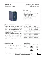


CT10.241, CT10.241-C1
CT-Series
3-P
HASE
,
24V,
10A,
240W
May 2018 / Rev. 2.0a DS-CT10.241-EN All values are typical figures specified at 3x 400Vac, 50Hz input voltage, symmetrical
phase voltages, 24V, 10A output load, 25°C ambient and after a 5 minutes run-in time unless otherwise noted.
www.pulspower.com Phone +49 89 9278 0 Germany
6/28
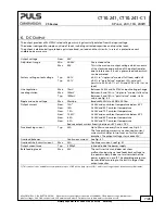
4.
DC-I
NPUT
Do not use the power supply with DC-input voltages.
5.
I
NPUT
I
NRUSH
C
URRENT
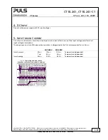
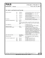
An active inrush limitation circuit limits the input inrush current after turn-on of the input voltage and after short
input voltage interruptions.
The charging current into EMI suppression capacitors is disregarded in the first microseconds after switch-on.
3AC 400V
3AC 480V
Inrush current
Max.
10A
peak
10A
peak
Temperature independent
Typ.
4A
peak
4A
peak
Temperature independent
Inrush energy
Max.
0.5A
2
s
0.5A
2
s
Temperature independent
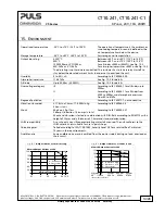
Fig. 5-1
Typical input inrush current
behaviour at nominal load and 25°C ambient
20ms/DIV
Input current 1A/DIV
Input voltage 500V/DIV
Output voltage