


CT10.241, CT10.241-C1
CT-Series
3-P
HASE
,
24V,
10A,
240W
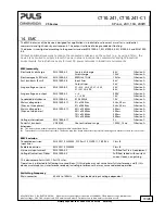
May 2018 / Rev. 2.0a DS-CT10.241-EN All values are typical figures specified at 3x 400Vac, 50Hz input voltage, symmetrical
phase voltages, 24V, 10A output load, 25°C ambient and after a 5 minutes run-in time unless otherwise noted.
www.pulspower.com Phone +49 89 9278 0 Germany
23/28
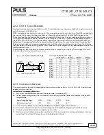
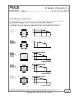
22.2.
O
UTPUT
C
IRCUIT
B
REAKERS
Standard miniature circuit breakers (MCB’s or UL 1077 circuit breakers) are commonly used for AC-supply systems and
may also be used on 24V branches.
MCB’s are designed to protect wires and circuits. If the ampere value and the characteristics of the MCB are adapted to
the wire size that is used, the wiring is considered as thermally safe regardless of whether the MCB opens or not.
To avoid voltage dips and under-voltage situations in adjacent 24V branches which are supplied by the same source, a
fast (magnetic) tripping of the MCB is desired. A quick shutdown within 10ms is necessary corresponding roughly to
the ride-through time of PLC's. This requires power supplies with high current reserves and large output capacitors.
Furthermore, the impedance of the faulty branch must be sufficiently small in order for the current to actually flow.
The best current reserve in the power supply does not help if Ohm’s law does not permit current flow. The following
table has typical test results showing which B- and C-Characteristic MCBs magnetically trip depending on the wire cross
section and wire length.
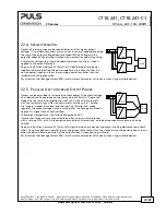
The following test results indicate the maximal wire length for a magnetic (fast) tripping. The wire length is always
two times the distance to the load (+ and – wire).
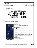
Fig. 22-3
Test circuit for maximum wire length
Test results for maximum wire length:
MCB
Power
Supply
AC
DC
+
-
+
-
Load
Wire length
S1...... Cault Simulation Switch
S1
0.75mm²
1.0mm²
1.5mm²
2.5mm²
C-2A
23m
28m
43m
69m
C-3A
18m
23m
34m
54m
C-4A
6m
12m
18m
28m
C-6A
3m
4m
6m
7m
C-8A
2m
3m
4m
5m
C-10A
1m
2m
3m
4m
B-6A
9m
14m
19m
33m
B-10A
4m
5m
6m
9m
B-13A
3m
4m
5m
8m
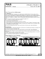
22.3.
C
HARGING OF
B
ATTERIES
The power supply can be used to charge lead-acid or maintenance free batteries. Two 12V SLA or VRLA batteries are
needed in series connection.
Instructions for charging batteries:
a)
Ensure that the ambient temperature of the power supply stays below 45°C.
b)
Set the output voltage, measured at no load and at the battery end of the cable, very precisely to the end-of-
charge voltage.
End-of-charge voltage
27.8V
27.5V
27.15V
26.8V
Battery temperature
10°C
20°C
30°C
40°C
c)
Use a 16A circuit breaker or a blocking diode between the power supply and the battery.
d)
Ensure that the output current of the power supply is below the allowed charging current of the battery.
e)
Use only matched batteries when putting 12V types in series.
f)
The return current to the power supply is typically 8mA. This return current can discharge the battery when the
power supply is switched off except in case a blocking diode is utilized.