Puls CT10.241 Скачать руководство пользователя страница 2


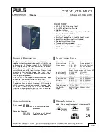
CT10.241, CT10.241-C1 


CT-Series 

3-P

HASE

,


24V,


10A,


240W 


May 2018 / Rev. 2.0a  DS-CT10.241-EN    All values are typical figures specified at 3x 400Vac, 50Hz input voltage, symmetrical  

phase voltages, 24V, 10A output load, 25°C ambient and after a 5 minutes run-in time unless otherwise noted. 

www.pulspower.com   Phone +49 89 9278 0    Germany 

2/28 


I

NDEX


Page 

Page 

1.


Intended Use .......................................................3


2.


Installation Instructions ......................................3


3.


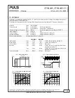
AC-Input...............................................................5


4.


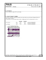
DC-Input...............................................................6


5.


Input Inrush Current ...........................................6
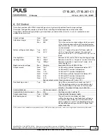
 

6.


DC Output............................................................7


7.


Hold-up Time .......................................................8


8.


Efficiency and Power Losses................................9
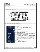
 

9.


Functional Diagram ........................................... 10


10.


Front Side and User Elements ........................... 10


11.


Connection Terminals ....................................... 11


12.


Lifetime Expectancy .......................................... 12


13.


MTBF .................................................................. 12
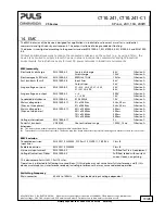
 

14.


EMC .................................................................... 13
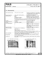
 

15.


Environment ...................................................... 14
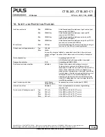
 

16.


Safety and Protection Features ........................ 15


17.


Dielectric Strength ............................................ 16
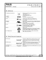
 

18.


Approvals ........................................................... 17


19.


Other Fulfilled Standards ................................. 17


20.


Physical Dimensions and Weight ..................... 18


21.


Accessories ........................................................ 19


21.1.


ZM1.WALL – Wall/Panel Mount Bracket . 19


21.2.


ZM13.SIDE - Side Mount Bracket ............. 20


21.3.


YRM2.DIODE - Redundancy Modules ...... 21


22.


Application Notes ............................................. 22


22.1.


Peak Current Capability ........................... 22


22.2.


Output Circuit Breakers ............................ 23


22.3.


Charging of Batteries ............................... 23


22.4.


Series Operation ....................................... 24


22.5.


Parallel Use to Increase Output Power .... 24


22.6.


Parallel Use for Redundancy .................... 25


22.7.


Operation on Two Phases ........................ 26


22.8.


Use in a Tightly Sealed Enclosure ............ 27


22.9.


Mounting Orientations ............................ 28


The information given in this document is correct to the best of our knowledge and experience at the time of 
publication. If not expressly agreed otherwise, this information does not represent a warranty in the legal sense of the 
word. As the state of our knowledge and experience is constantly changing, the information in this data sheet is 
subject to revision. We therefore kindly ask you to always use the latest issue of this document (available under 
www.pulspower.com). 
No part of this document may be reproduced or utilized in any form without our prior permission in writing. 


T

ERMINOLOGY AND 

A

BBREVIATIONS


PE and 

 symbol


PE is the abbreviation for 

P

rotective 

E

arth and has the same meaning as the symbol 

Earth, Ground 

This document uses the term “earth” which is the same as the U.S. term “ground”. 

T.b.d.


To be defined, value or description will follow later. 

AC 400V 

A figure displayed with the AC or DC before the value represents a nominal voltage with 

standard tolerances (usually ±15%) included.  
E.g.: DC 12V describes a 12V battery disregarding whether it is full (13.7V) or flat (10V) 

400Vac 

A figure with the unit (Vac) at the end is a momentary figure without any additional 
tolerances included.  

50Hz vs. 60Hz


As long as not otherwise stated, AC 380V and AC 400V parameters are valid at 50Hz and AC 
480V parameters are valid at 60Hz mains frequency. 

may


A key word indicating flexibility of choice with no implied preference. 

shall


A key word indicating a mandatory requirement. 

should


A key word indicating flexibility of choice with a strongly preferred implementation. 

Содержание CT10.241

Страница 1: ...ieved by a synchronous rectification and further technological design details The CT10 241 C1 is equipped with conformal coated pc boards preferred for applications in harsh areas The C Series include...

Страница 2: ...orrect to the best of our knowledge and experience at the time of publication If not expressly agreed otherwise this information does not represent a warranty in the legal sense of the word As the sta...

Страница 3: ...e factory for inspection The tripping of an internal fuse is caused by an internal defect Install device in an enclosure providing protection against electrical mechanical and fire hazards Install the...

Страница 4: ...ircuits up to 32A IEC and 30A UL without additional protection device If an external fuse is utilized do not use circuit breakers smaller than 6A B or C Characteristic to avoid a nuisance tripping of...

Страница 5: ...voltage Typ 3x 260Vac Steady state value see Fig 3 1 Shut down voltage Typ 3x 185Vac Steady state value see Fig 3 1 External input protection See recommendations in chapter 2 3AC 400V 3AC 480V Input...

Страница 6: ...NRUSH CURRENT An active inrush limitation circuit limits the input inrush current after turn on of the input voltage and after short input voltage interruptions The charging current into EMI suppressi...

Страница 7: ...d regulation Max 100mV Between 0 and 10A in single use mode static value Typ 1000mV Between 0 and 10A in parallel use mode static value see Fig 6 2 Ripple and noise voltage Max 50mVpp Bandwidth 20Hz t...

Страница 8: ...30A 21 12 3 6 15 24 27 Adjustment Range Output Current Extra current for 20ms Continuous current Factory setting Output Voltage Parallel Use typ 22V 0 4 8 23V 24V 25V 29V 26V 27V 28V 12A 10 6 2 Adjus...

Страница 9: ...3 5W 22 8W At 24V 12A 3 phase operation The average efficiency is an assumption for a typical application where the power supply is loaded with 25 of the nominal load for 25 of the time 50 of the nomi...

Страница 10: ...gle Parallel 10 FRONT SIDE AND USER ELEMENTS Fig 10 1 Front side A Output Terminals Positive output two identical poles Negative return output two identical poles B Input Terminals L1 L2 L3 Line input...

Страница 11: ...m2 Max 4mm2 American Wire Gauge AWG 20 10 AWG 20 10 Max wire diameter including ferrules 2 8mm 2 8mm Recommended tightening torque 1Nm 9lb in 1Nm 9lb in Wire stripping length 7mm 0 28inch 7mm 0 28inch...

Страница 12: ...10A and 25 C 2 phase operation 379 000h 410 000h At 24V 5A and 25 C 2 phase operation 102 000h 119 000h At 24V 12A and 25 C 2 phase operation 13 MTBF MTBF stands for Mean Time Between Failure which is...

Страница 13: ...1 L2 L3 PE 2kV 4kV Criterion A Criterion A Surge voltage on output EN 61000 4 5 PE 500V 1kV Criterion A Criterion A Conducted disturbance EN 61000 4 6 0 15 80MHz 10V Criterion A Mains voltage dips Dip...

Страница 14: ...er voltage category III According to IEC 60664 1 for altitudes up to 2000m II According to IEC 60664 1 for altitudes from 2000 to 6000m and atmospheric pressures from 80 to 47kPa Degree of pollution 2...

Страница 15: ...ndant circuit limits the maximum output voltage The output shuts down and automatically attempts to restart Class of protection I According to IEC 61140 A PE Protective Earth connection is required De...

Страница 16: ...ed in the field using the appropriate test equipment which applies the voltage with a slow ramp 2s up and 2s down Connect all input terminals together as well as all output poles before conducting the...

Страница 17: ...006 Applicable for altitudes up to 2000m Marine GL Germanischer Lloyd classified and ABS American Bureau for Shipping PDA Environmental category C EMC2 Marine and offshore applications SEMI F47 SEMI F...

Страница 18: ...S AND WEIGHT Width 62mm 2 44 Height 124mm 4 88 Depth 117mm 4 61 The DIN rail height must be added to the unit depth to calculate the total required installation depth Weight 750g 1 65lb DIN Rail Use 3...

Страница 19: ...ZM1 WALL WALL PANEL MOUNT BRACKET These brackets are used to mount the device on a flat surface or panel without utilizing a DIN rail The two aluminum brackets and the black plastic slider of the uni...

Страница 20: ...bracket is used to mount the device sideways with or without utilizing a DIN rail to save installation depth The two aluminum brackets and the black plastic slider of the unit have to be detached so t...

Страница 21: ...device is equipped with two input channels each 10A nominal which are individually decoupled by utilizing diode technology The output can be loaded with nominal 20A The device does not require an addi...

Страница 22: ...on applies when starting a capacitive load The peak current capability also ensures the safe operation of subsequent circuit breakers of load circuits The load branches are often individually protecte...

Страница 23: ...which B and C Characteristic MCBs magnetically trip depending on the wire cross section and wire length The following test results indicate the maximal wire length for a magnetic fast tripping The wi...

Страница 24: ...en using multiple devices 22 5 PARALLEL USE TO INCREASE OUTPUT POWER Devices can be paralleled to increase the output power The output voltage of all devices shall be adjusted to the same value 100mV...

Страница 25: ...rease when using multiple devices N 1 Redundancy Redundant systems for a higher power demand are usually built in a N 1 method E g four devices each rated for 10A are paralleled to build a 30A redunda...

Страница 26: ...uitability of your individual application Using only two legs of a 3 phase system is not included in the agency approval Therefore additional investigations might be necessary during the approval proc...

Страница 27: ...ambient temperature for the device In the following test setup the device is placed in the middle of the box no other heat producing items are inside the box The load is placed outside the box The te...

Страница 28: ...ting orientation The following curves give an indication for allowed output currents for altitudes up to 2000m 6560ft Fig 22 10 Mounting Orientation A Standard orientation Power Supply OUTPUT INPUT Al...

Отзывы: