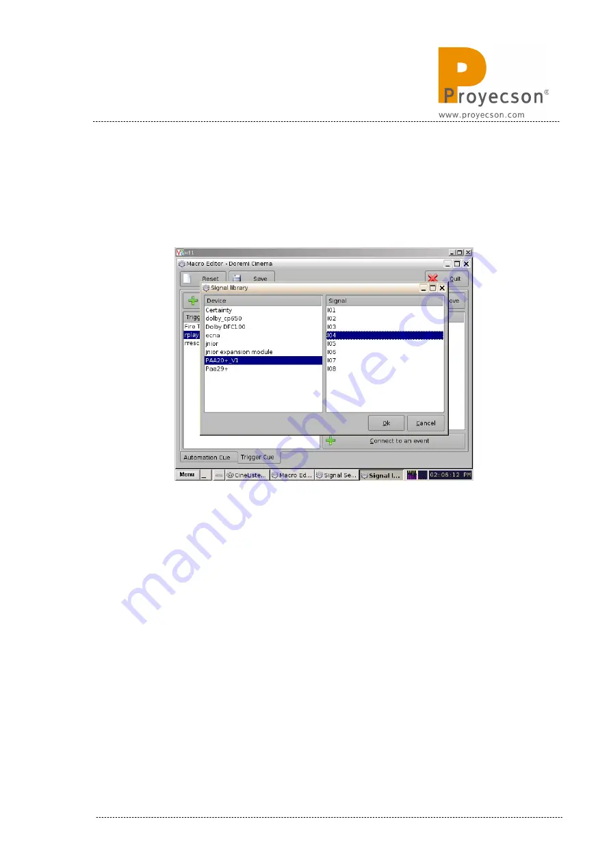
4. Pressing this button you will open the “Signal Library” pop-up window,
you must select the “PAA20+” in the “driver” window and choose the
appropriate input of the PAA20+ in the “Signal” window. Every signal
matches the physical input with the same number in the device. You
may see an example for the Input 4 in
Figure 8.2.5D
.
Figure 8.2.5D
5. Pressing the Ok button of the “Signal library” window you will go back
to the “Signal Setup” window, but with the “Signal name” filled in with
your previous chosen input selection. You can see the example for the
Input 4 in
Figure 8.2.5E
. Click on the Ok button to finish the creation
of the trigger cue.
INSTALLATION MANUAL: PAA20+ V 2.0 (10/2021)
63
Содержание PAA20+
Страница 1: ...INSTALLATION MANUAL PAA20 V 2 0 ...
Страница 40: ...Figure 7 2 7D INSTALLATION MANUAL PAA20 V 2 0 10 2021 40 Figure 7 2 7E Figure 7 2 7F ...
Страница 110: ...9 2 OUTPUT 2 CONNECTOR Figure 9 2A Picture 9 2B INSTALLATION MANUAL PAA20 V 2 0 10 2021 110 ...
Страница 111: ...9 3 OUTPUT 3 CONNECTOR Figure 9 3A Figure 9 3B INSTALLATION MANUAL PAA20 V 2 0 10 2021 111 ...
Страница 112: ...9 4 INPUT CONNECTOR Figure 9 4A Picture 9 4B INSTALLATION MANUAL PAA20 V 2 0 10 2021 112 ...
Страница 114: ...9 5 2 INPUT WITH A POSITIVE COMMON Picture 9 5 2A INSTALLATION MANUAL PAA20 V 2 0 10 2021 114 ...


