background image

Version 1.0

41

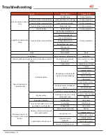
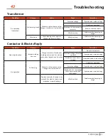
Troubleshooting

41

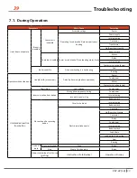
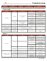
Power Cable

Motor

Condition

Reason

Action

Cause

Correction

No operation

Abnormal supply voltage

Power supply

Improper power supply

Check power supply regularly

Condition

Reason

Action

Cause

Correction

No operation

Wire break

Repair or change cable 

if broken 

Strong force exerted

Firmly fix on cable support or 

other equipment

(2 or more)

Use anti-vibration cable in 

movable part.

Twisted, knotted

Straighten twists and knots

Interference with other 

equipment

Use fixed cable and avoid 

outside interference

Overheating

Check cables, exchange if 

overheating

Temperature rise due to 

off-capacity

Adopt the proper cable

Binding cable used

Do not use binding cable

Starting slow or no operation

Off-capacity 

Check cable diameter, replace 

cable if diameter is too small

Voltage drop 

Adopt proper cable

Operation only in free load 

(single phase)      

1 wire break or 

overheating

Refer to above break or overheating item

Movement did not correspond 

with switch button (opposite)

Power line 

connection error

Replace wires

Wiring assembly error

Connect wire as per wiring 

diagram

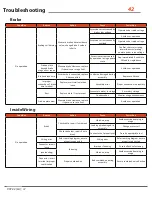
Condition

Reason

Action

Cause

Correction

No operation

Coil burning   (above 

2 phase)

Measure phase resistance value; 

change motor if value is infinite.

Excessive current caused by 

high or low voltage

Operate under rated voltage

Excessive current caused by 

overload

Operate under rated voltage

Beyond short-term rating 

and intermittent cycle rating

Short-term rating, intermittent 

cycle rating, operate under 

rated voltage

Avoid over-operation

Excessive current caused by 

brake

Refer to brake

Lead wire break 

(above 2 phase)

Measure phase resistance value; 

change motor if value is infinite.

Lead wire broken in 

assembly

Change motor coil

Vibration, drop

Avoid excessive bumping in 

usage

Operation only in free load 

(single phase state)

Coil burning 

(1 phase only)

Measure phase resistance value; 

change motor if value is infinite

Poor electric isolation 

Ensure foreign matter does not 

enter motor

Leading wire break 

(1 phase only)

Measure phase resistance value; 

change motor if value is infinite

Leading wire break in 

assembly

Change motor coil 

Vibration, drop

Avoid excessive bumping 

V.07.22 [LA]

Содержание PWJTHF

Страница 1: ...Reg U S TM Off User s Manual Manual de usuario Safety Warnings Advertencias de seguridad PWJTHF PWJTHT Single phase models...

Страница 2: ...This page intentionally left blank...

Страница 3: ...formation about the application use and requirements provided by the client It is not the responsibility of Prowinch LLC to verify the accuracy of the given information It is the sole and exclusive re...

Страница 4: ...all be determined by tests with an empty hook traveling at increasing speeds up to the maximum speed The actuating mechanism of the limit switch must be located so that it will trip the switch under a...

Страница 5: ...PONSIBILITY to consider all risk factors and follow all the equipment related ASME B30 standard which comprises the following volumes B30 1 Jacks Industrial Rollers Air Casters and Hydraulic Gantries...

Страница 6: ...O NOT Operate the hoist unless the hook travel limit devices function properly Test without a load PRE SHIFT 11 DO NOT Operate the hoist with twisted kinked damaged dirty or unlubricated chain or rope...

Страница 7: ...rope for proper reeving and that rope parts are not twisted LIMIT SWITCHES Ensure that all limit devices stop lifting motion before the load block or chain rope stop strikes the hoist OIL LEAKAGE Che...

Страница 8: ...nections 24 Install Trolley models with trolley 26 Adjust Trolley Width models with trolley 26 Install Trolley into Beam models with trolley 26 Supply Voltage 26 Operation 27 Qualified Operator 27 Han...

Страница 9: ...46 Chain Wheel 47 Load pulley and empty pulley 47 Chain guide 47 Chain wheel junction part 47 Bearing 47 Trolley 48 Electric Trolley 48 Manual Trolley 44 Wiring Diagram 49 Conventional Hoist wiring di...

Страница 10: ...ed according to this User Manual Respect all warnings for personal and third party safety The inadequate operation of this equipment may cause injuries or damage to the equipment Read and understand t...

Страница 11: ...hoist before operating equipment Wear appropriate clothing Do not wear jewelry or loose clothes as they may attach to chain or hook Wear leather gloves Wear non slip safety shoes helmet and eye protec...

Страница 12: ...or extend the chain Never use the load chain or hook as an electrical or welding ground Never remove the labels placed on the electric chain hoist Never use the hoist to lift the load at an angle nor...

Страница 13: ...t others from doing so 8 Always verify the correct hoist installation before use 6 Do not use the hoist if exposed to rain snow or lightning 2 Check the proper crimp of the electrical connections 3 Pe...

Страница 14: ...which the hoist is designed This range is indicated in this manual and may vary depending on the model Exposure to water sand a corrosive environment or other potentially harmful elements may damage...

Страница 15: ...he temperature or humidity exceeds the range stated in the Specification Chart Our hoists are designed to lift loads vertically under normal atmospheric and working conditions Item Specs Operating tem...

Страница 16: ...7 5 12 5 75 15 100 H3 General machine shop fabricating assembly storage and warehousing Loads and utilization are randomly distributed Total running time is at most 25 of the work period 15 25 150 30...

Страница 17: ...mit 1 3 H4 H5 Specifications Model PWJTHF300 PWJTHF500 PWJTHF800 Capacity lb 300 500 800 Lifting Speed ft min 14 7 7 Motor Power W 160 160 200 Insulation Grade IP55 Power Supply 120VAC Control Voltage...

Страница 18: ...Chain 5x15 5x15 5x15 Net Weight lb 28 40 40 Basic Dimensions in H 5 4 5 4 5 7 A 15 16 16 7 B 14 14 14 0 D 4 3 4 3 4 3 E 2 8 2 8 2 8 Model Dimension in A B C D E F G H L K M N PWJTHF300 14 5 14 1 6 4 3...

Страница 19: ...Version 1 0 19 Specifications 19 V 07 22 LA...

Страница 20: ...Version 1 0 Specifications 20 20 V 07 22 LA...

Страница 21: ...per year for normal usage more frequently for heavier use or severe conditions WARNING PWWA001 V1 0 Failure to keep the load chain clean and well lubricated will void the warranty Lubricate the load...

Страница 22: ...ue Do not use conductors smaller than those listed in this User Manual to supply power to hoist Never bypass limit switches remove limit switch stops or alter limit switch devices Hoist should be care...

Страница 23: ...on pin has been installed correctly Remarks If the hoist is equipped with an electric trolley the upper hook can be removed 4 3 2 Assemble chain bag Fig 4 1 4 3 3 Link the power supply and operate the...

Страница 24: ...protect power supply Do not use power supply cables with solid conductors An improper or insufficient ground connection creates an electrical shock hazard when touching any part of hoist or trolley Op...

Страница 25: ...sting disk 3 Install suspension pin into hanger T The nameplates of hoist and trolley should be in the same direction 4 Install additional gaskets into suspension pin before inserting it into lateral...

Страница 26: ...bit wheel onto surface of beam d Unload brake stopper from hole B and insert into hole A Do not forget to bend cotter pin 3 7 Supply Voltage Check supply voltage everyday before use If voltage varies...

Страница 27: ...read understand or speak language of security labels ID Plate and User Manual of equipment Does not meet legal age requirements Has visual or hearing impairments Experiences mental heart or other hea...

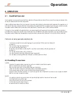
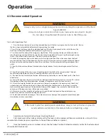
Страница 28: ...any other button is pressed The hoist should not start again 4 Rotate the emergency stop switch clockwise to its original position When it bounces back the hoist may be restarted If any of the above...

Страница 29: ...er load until it is secured on resting surface Avoid hitting surface at high speed If necessary stop movement before reaching surface and gradually lower to land load NEVER leave load suspended withou...

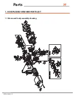
Страница 30: ...Version 1 0 Parts 30 30 1 H3 EXPLODED VIEW AND PARTS LIST 1 1 Motor and body assembly drawing V 07 22 LA...

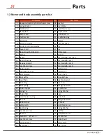
Страница 31: ...anging Bracket 52 Intermediate gear B 16 Lock Plate screw 53 Intermediate gear A 17 Chaing guide 54 High gear B 18 Load Chain Wheel 55 High gear A 19 Limit Stopper 56 Pinion shaft 20 Limit baffle 57 W...

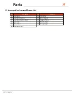
Страница 32: ...parts list No Part Name No Part Name 75 Lower Hook 81 Flat Washer 76 Lower Hook Housing 82 Spring Washer 77 Lower Hook Housing Cover 83 Hexagon thin nut 78 Swim Shaft 84 Chain hoist pin 79 Chain Whee...

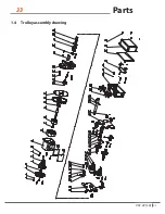
Страница 33: ...Version 1 0 33 Parts 33 1 4 Trolley assembly drawing V 07 22 LA...

Страница 34: ...otherboard set 14 Rotor Shaft 46 Spring Washer 15 Bearing 47 Non metallic hexagonal lock nut 16 Motor base plate 48 Trolley axis adjustment ring 17 Gasket 49 Trolley board set 18 Limit switch gasket 5...

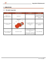
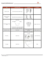
Страница 35: ...d with cleaning repairing and replacing Record serial number for replacing Deformation or damage of body parts Visual check No remarkable deformation damage defect or chap Replace parts which are defo...

Страница 36: ...check No deep cut No Deformation No deformation No Wind No Chap Replace load chains Confirm chain is not stuck to welding spatters by visually inspecting it Rust and corrosion Visual check No remarkab...

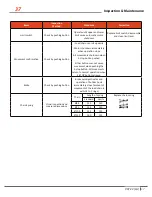
Страница 37: ...ly when operation stops All movements shutdown when E stop button pushed Other buttons cannot cause movement when pushing the E stop button All movements return to normal operation when E STOP button...

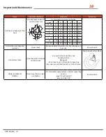
Страница 38: ...0 25 142 95 155 98 150 115 Deformation damage and corrosion Visual check No remarkable deformation harmful damage and corrosion Replace hook Hook safety block Visual inspection fold and unfold actions...

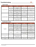
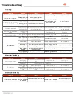
Страница 39: ...only Unable to lift motor roar Default phase single phase operation Power Feed power Motor Contactor junction fusing Slow lifting Low voltage Feed power Unintended reaction from button Inverse reactio...

Страница 40: ...nt not properly grounded Proper electric connec tion Does not operate in non load state Brake inaudible Supply power Supply power voltage Operating circuit break off electric parts overheating Cables...

Страница 41: ...pposite Power line connection error Replace wires Wiring assembly error Connect wire as per wiring diagram Condition Reason Action Cause Correction No operation Coil burning above 2 phase Measure phas...

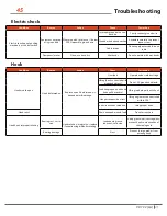
Страница 42: ...erminal Replace insert terminal when loose Assembly error Proper connection in assembly Rust Replace brake if rust present Exposure to water in storage Ensure dry storage Condensation Monitor usage en...

Страница 43: ...Reason Action Cause Correction Non stop activation Junction welding burn out Change contactor if continuous welding or burn out For electric reply visual inspection of junction Do not over operate Exc...

Страница 44: ...is inversely connected Swap 2 wire power cords Wiring error Properly connect wire power cords as per wiring diagram Condition Reason Action Cause Correction No operation Contactor Emergency button is...

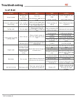
Страница 45: ...open Hook deformation Replace hook if deformation is beyond permitted range Overload Operate under rated voltage Lifting hook connected with grounded object Do not lift grounded objects Load hanging...

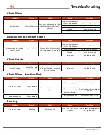
Страница 46: ...sive operation Overload Use under rated load Incline pull Ensure proper pull direction Wear of load pulley and empty pulley Refer to load pulley and empty pulley Extension of pitch Measure pitch and r...

Страница 47: ...ation Avoid excessive operation Overload Use under rated load Incline pull Avoid incline pull Condition Reason Action Cause Correction Increased shaking Wear of chain guide and guide pulley Measure be...

Страница 48: ...proper adjustment circle Confirm adjustment circle number and insert position Insufficient confirmation Install correctly Wear of wheel Confirm wear degrees Traveling surface has bump Confirm regularl...

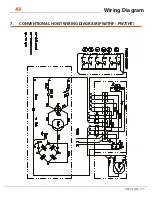
Страница 49: ...49 Wiring Diagram 49 7 CONVENTIONAL HOIST WIRING DIAGRAM PWJTHF PWJTHT V 07 22 LA...

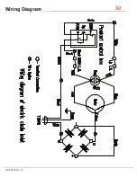
Страница 50: ...Wiring Diagram 50 50 V 07 22 LA...

Страница 51: ...Mexico S A de C V Vicente Guerrero No 403 Col San Miguel Apodaca Nuevo Leon Mexico C P 66649 52 81 8244 1351 Prowinch Colombia SAS www prowinch co Cl 163a 20 28 Bogot Colombia 57 1 7034035 Proveedora...

Отзывы: