Appendix A System Diagrams
SP-6150/6155 SERIES USER MANUAL
Page: A-2
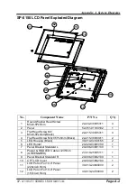
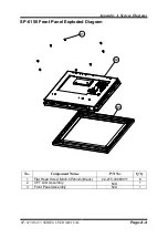
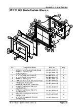
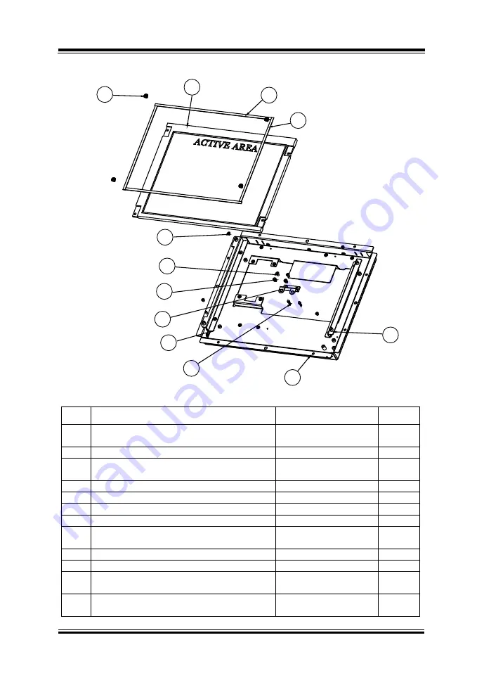
SP-6150 LCD Panel Exploded Diagram
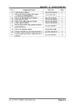
No.
Component Name
P/N No.
Q’ty
1
Round Washer Head Screw
M3x0.5Px5mm
22-242-30005311
4
2
Panel
52-351-01104102
1
3
Flat Head Screw #2 /
M3x0.5Px4mm(Black)
22-215-30005311
4
4
Flat Head Screw M3x0.5Px6mm (Black)
22-215-30060011
2
5
LED Housing (Black)
30-014-04100165
2
6
LED Holder
20-029-03003130
1
7
Panel Bracket Standard L
20-006-03001130
1
8
Power & HDD LED Cable L=235mm
(GREEN&RED)
27-018-25005111
1
9
Panel Bracket Standard R
20-006-03002130
1
10
CPT LCD Cover
20-004-03062130
1
11
LCD Poron For 10.4" Panel
(220x4x0.5mm)
30-013-24600000
2
12
LCD Poron For 10.4" Panel
(167x4x0.5mm)
30-013-24700000
2
02
01
11
12
03
04
05
06
09
07
08
10
Содержание SP-6150
Страница 9: ...vi Flash BIOS Update B 25...
Страница 17: ...Chapter 2 Getting Started SP 6150 6155 SERIES USER MANUAL Page 2 5 Quarter View...
Страница 20: ...Chapter 2 Getting Started SP 6150 6155 SERIES USER MANUAL Page 2 8 Quarter View...
Страница 32: ...Chapter 3 Hardware Configuration SP 6150 6155 SERIES USER MANUAL Page 3 9 Jumper diagrams Jumper settings...
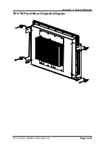
Страница 130: ...Appendix A System Diagrams SP 6150 6155 SERIES USER MANUAL Page A 10 SP 6155 Panel Mount Exploded Diagram...

