Chapter 3 Hardware Configuration
SP-6150/6155 SERIES USER MANUAL
Page: 3-36
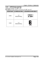
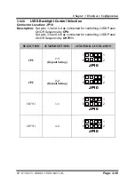
3.5.28
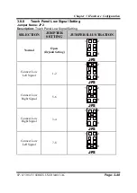
LVDS Backlight Control Selection
Connector Location: JP10
Description:
Set pins 1-3 and 2-4 as connected for controlling LVDS Panel
On/Off Sequence by
CPU
.
Set pins 3-5 and 4-6 as connected for controlling LVDS Panel
On/Off Sequence by
CH7511
.
SELECTION
JUMPER SETTING
JUMPER ILLUSTRATION
CPU
1-3
(Default Setting)
JP10
CPU
2-4
(Default Setting)
JP10
CH7511
3-5
JP10
CH7511
4-6
JP10
1
2
7
8
1
2
7
8
1
2
7
8
1
2
7
8
Содержание SP-6150
Страница 9: ...vi Flash BIOS Update B 25...
Страница 17: ...Chapter 2 Getting Started SP 6150 6155 SERIES USER MANUAL Page 2 5 Quarter View...
Страница 20: ...Chapter 2 Getting Started SP 6150 6155 SERIES USER MANUAL Page 2 8 Quarter View...
Страница 32: ...Chapter 3 Hardware Configuration SP 6150 6155 SERIES USER MANUAL Page 3 9 Jumper diagrams Jumper settings...
Страница 130: ...Appendix A System Diagrams SP 6150 6155 SERIES USER MANUAL Page A 10 SP 6155 Panel Mount Exploded Diagram...

