MVI56-DEM
♦
ControlLogix Platform
Reference
Honeywell DE Communication Module
Page 44 of 80
ProSoft Technology, Inc.
March 6, 2008
Normal Data Transfer
Normal data transfer includes the transferring of data received by or to be
transmitted to the DE driver. This data is transferred through read (input image)
and write (output image) blocks. Refer to Module Configuration for a description
of the data objects used with the blocks and the ladder logic required. The
following topics discuss the structure and function of each block.
Read Block
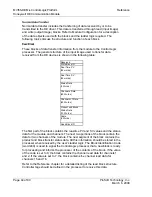
These blocks of data transfer information from the module to the ControlLogix
processor. The general structure of the input image used to transfer data
received from the DE devices is shown in the following table:
Reserved
Write Block ID
Real Time PV
(32 words)
Real Time SV
(32 words)
Status Data
(3 Words)
Channel x Data
(82 Words)
Channel x+1 Data
(82 Words)
Product and Block
Status Data
(13 Words)
Spare
(3 Words)
Read Block ID
The first part of the block contains the real-time PV and SV values and the status
data for the module and channels. The next two portions of the block contain the
data for two channels of the module. The next segment of the block contains the
product and block transfer status data. All this information should be stored in the
processor when received by the user's ladder logic. The Block Identification Code
(word 249) is used to signal the ControlLogix processor that a new block is ready
for processing and informs the processor of the contents of the block. If the value
of the code is set to 0, the block contains the channel read data for channels 1
and 2. If the value is set to 7, the block contains the channel read data for
channels 15 and 16.
Refer to the Reference chapter for a detailed listing of the read block structure.
Controller tags should be defined in the processor to receive this data.


