


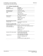


MVI56-DEM
♦
ControlLogix Platform
Reference
Honeywell DE Communication Module
Page 42 of 80
ProSoft Technology, Inc.
March 6, 2008
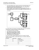
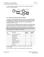
Main Logic Loop
Upon completing the power up configuration process, the module enters an
infinite loop that performs the functions shown in the following diagram.
Call I/O Handler
Call CFG/DEBUG Port
Driver
Call Network
Slave Drivers
Call I/O Handler
Transfers data between the module and processor
(user, status, etc.)
Call Serial Port Driver
Rx and Tx buffer routines are interrupt driven. Call to
serial port routines check to see if there is any data
in the buffer, and depending on the value, will either
service the buffer or wait for more characters.
Call Network Slave Drivers
Respond to messages received.
From Power Up Logic
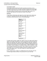
Backplane Data Transfer
The MVI56-DEM module communicates directly over the backplane. Data
travels between the module and the ControlLogix processor across the
backplane using the module's input and output images. The update frequency of
the data is determined by the scan rate defined by the user for the module and
the communication load on the module. Typical updates are in the range of 1 to
10 milliseconds.
Data received by the DE driver is placed in the module's input image. This data is
processed by the ladder logic in the ControlLogix processor. The input image for
the module is set to 500 bytes. This large data area permits fast throughput of
data between the module and the processor.
The processor inserts data in the module's output image to transfer to the
module. The module's program extracts the data and transmits the data out to
the DE driver to the DE instruments. Additionally, the ControlLogix processor can
send special control blocks to the module to instruct it to perform a special task.
The output image for the module is set to 496 bytes. This large data area permits
fast throughput of data from the processor to the module.


