MVI56-DEM
♦
ControlLogix Platform
Reference
Honeywell DE Communication Module
Page 64 of 80
ProSoft Technology, Inc.
March 6, 2008
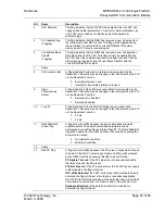
Bit Name
Description
14
PV Under Range
Flag
This flag is set whenever the PV value is under 0%.
15
PV Over Range
Flag
This flag is set whenever the PV value is over 100%.
5.8.2 Device Status Flags #2
The bits in this word indicate the current mismatch status for each data variable
which is verified. When the bit is set (1) the variable is in a mismatched condition.
The mismatch may be cleared by performing a download to the instrument or by
performing an upload (copying the read data base to the write data base). If the
PLC database is downloaded to the instrument, the mismatch condition will not
clear until the complete database has been read back from the instrument.
Bit Description
0
LRV - Mismatch
1
URV - Mismatch
2
URL - Mismatch
3
Damping - Mismatch
4
DE Config - Mismatch
5
PV Char - Mismatch
6
Sensor Type - Mismatch
7
Tag ID - Mismatch
8
PV Number - Mismatch
9
Number of PV Values - Mismatch
10
Cold Junction Ref - Mismatch
11
Open Thermocouple Detect - Mismatch
12
Freq 50 - Mismatch
13 Spare
14 Spare
15 Spare
Special DB byte
Bit Description
0
Initial Power-up Data base
1
1st DB Capture in progress
2
4 Byte Data Base
3
No DE Data Available
4
SFC Write Detected
5 Output
Mode
6 Not
Used
7 Not
Used


