MVI46-PDPS
♦
SLC Platform
Configuring the Module with RS Logix 500
Profibus DP Slave Communication Module
Page 26 of 72
ProSoft Technology, Inc.
April 30, 2008
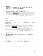
2.4 [MODULE]
The module section contains the data that applies to the whole module and
includes the backplane data transfer parameters.
[Module]
Module Name
: MVI46-PDPS Communication Module DEFAULT
The following table describes the content of this section:
[Section]/Item Value
Range
Description
[MODULE]
Configuration header for general module information
Module Name:
Up to 80
chars
Name of the module for use on reports. Use this
parameter to identify your module in your system.
2.5 [BACKPLANE]
The backplane section contains the data that applies to the backplane data
transfer parameters.
[Backplane]
Read Register Count : 122 #Number of words to move from MVI to Processor
(Profibus Output)
Write Register Count : 122 #Number of words to move from Processor to MVI
(Profibus Input)
[Section]/Item Value
Range
Description
[BACKPLANE]
Configuration header for general Backplane information
Read Register Count
122
0 to 122 Number of words to move from the PDPS Module to
controller tags in the processor (PROFIBUS Output)
Write Register Count
122
0 or 122 Number of words to move from controller tags in the
processor to the PDPS module (PROFIBUS Input)
2.6 [PROFIBUS
SLAVE]
The PROFIBUS Slave section contains the data that applies to the PROFIBUS
Slave parameters.
[Profibus Slave]
Slave Address : 6 #Profibus node address for slave (0-125)
Swap Input Bytes : No #Swap bytes in input image (Yes or No)
Swap Output Bytes : No #Swap bytes in output image (Yes or No)
Comm Failure Mode : 1 #0=x-fer on comm fail, 1=no x-fer on fail
Comm Timeout Multiplier : 1 #(1 to 10) * 125 mSec communication timeout
Use Database Paging : N # Y or N. Enables or disable paging.
2.6.1 Slave
Address
0 to 125
The parameter specifies the node address on the PROFIBUS network for the
slave emulated in the module. Each node on the network must have a unique
address.


