background image

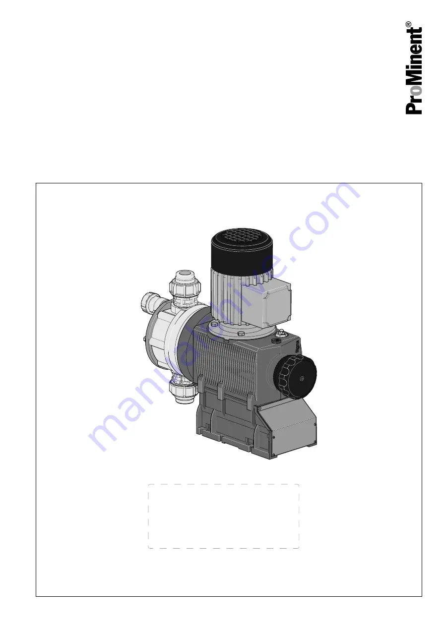
Diaphragm motor-driven metering pump

Sigma/ 2 Basic type S2Ba

Operating instructions

P_SI_0074_SW

Target group: Minimally instructed personnel

EN

Original operating instructions (2006/42/EC)

Part no. 985908

Version: BA SI 107 07/22 EN

Please carefully read these operating instructions before use. · Do not discard.

The operator shall be liable for any damage caused by installation or operating errors.

The latest version of the operating instructions are available on our homepage.

Содержание Sigma / 2 Basic S2Ba

Страница 1: ...nnel EN Original operating instructions 2006 42 EC Part no 985908 Version BA SI 107 07 22 EN Please carefully read these operating instructions before use Do not discard The operator shall be liable f...

Страница 2: ...to the cor rect operation of the unit or is intended to make your work easier Safety notes Safety notes are identified by pictograms see Safety Chapter These operating instructions conform to current...

Страница 3: ...uipment and control elements 26 5 Functional description 28 5 1 Pump 28 5 2 Liquid end 28 5 3 Integral relief valve 28 5 4 Multi layer safety diaphragm 29 6 Assembly 30 6 1 Assembly of the motor with...

Страница 4: ...versions 68 16 Diagrams for setting the metering capacity 69 17 Dimensional drawings 70 18 Potential equalisation drawings for Sigma Basic Type 72 19 Motor data sheet standard motor 73 20 Exploded dra...

Страница 5: ...bar 4 with relief valve FPM seal no valve springs 5 with relief valve FPM seal with valve springs 6 with relief valve EPDM seal no valve spring 7 with relief valve EPDM seal with valve spring H Hygien...

Страница 6: ...265 V 50 60 Hz 4 with stroke control motor 0 4 20 mA 85 265 V 50 60 Hz FPM fluorine rubber Standard with hose sleeve in the bypass Threaded connection on request ATEX specification refer to the namep...

Страница 7: ...Sigma 2 The pump designation is II 3G Ex h IIB T4 Gc The pump label corresponds to Unit group II the pump may only be used in overground production systems which are not at risk from firedamp The inse...

Страница 8: ...risk from firedamp The inserted pump label 2G Ex h does not need to be discussed here The pump label is shown in the example Explosion group IIC and Temperature class T4 The Tab 1 Example of the divi...

Страница 9: ...it uation If this is disregarded you are in a life threatening situation and this can result in serious inju ries CAUTION Denotes a possibly dangerous sit uation If this is disregarded it could result...

Страница 10: ...ance List in the Product Catalogue or at www prominent com n All other uses or modifications are prohibited n The pump is not designed to meter gaseous media and solids n The pump is not intended for...

Страница 11: ...cal technician is employed and be conversant with the relevant standards and regulations Instructed person An instructed person is deemed to be a person who has been instructed and if required trained...

Страница 12: ...isconnect the pump from the mains power supply and ensure that it cannot be switched on again by unauthorised persons Ensure that the system is at atmospheric pressure before commencing any work on hy...

Страница 13: ...nsi bility of the operator to create the legal framework for the safe operation of the system or system component such as for example the preparation of operating instructions operator s duties 2 5 Is...

Страница 14: ...over 2 bar and only if the operator takes appropriate safety measures Rupture signalling must switch off the pump immedi ately n Do not expose the ATEX design to any sources of ionising radiation or e...

Страница 15: ...h knowledge of ATEX explosion protection An electrical technician with an additional explosion protection qualification should be specifically trained for the field of work in which they are employed...

Страница 16: ...ing Paint should not be applied too thickly Only clean plastic parts with a damp cloth Provide a temperature monitor on the dosing head with feed chemical with critical friction properties The custome...

Страница 17: ...stroke sensor Refer to the documentation for the proximity switch elec trical installation maintenance WARNING ATEX pumps in areas at risk from explosion The operator must observe the Operator Direct...

Страница 18: ...as at risk from explosion If abrasive media is being metered it will escape as soon as all layers of the diaphragm have eroded through Wire the electrical diaphragm rupture indicator to immediately st...

Страница 19: ...and eliminate the cause Check the correct operation of the relief valve down stream of the pump In premises at risk from explo sion the relief valve should prevent the gear from becoming overloaded a...

Страница 20: ...ance with the chapter Installation electrical Refer to its documentation Sensor name NJ1 5 8GM N Check the pump installation for n leaks n Abnormal noises or squeaks n abnormal temperatures n abnormal...

Страница 21: ...ith higher installation heights 2 7 6 Safety equipment WARNING The following safety information must be affixed to pumps that include parts made of electrically non conducting plastic Ensure that the...

Страница 22: ...from explosion Please refer in this respect to the operating instructions design test certifi cates and other documentation for the bought in parts 2 8 Explanation of the ATEX label in accordance wit...

Страница 23: ...plosion groups and temperature classes on page 23 is shown as an example the pump can be used for ethyl ether or a comparable gas refer to the material safety data sheet for the gas or your explosion...

Страница 24: ...losion groups and temperature classes on page 23 shows the following the pump can be used for all gases of Explosion group IIC and Temperature class T4 refer to your explosion protection document The...

Страница 25: ...per storage or transportation The unit should only be stored or transported in a well packaged state preferably in its original pack aging Only transport the unit when the red gear bleeding plug is pu...

Страница 26: ...ment and control elements S2Ba 1 Drive motor 2 Drive unit 3 Stroke length adjustment knob 4 Liquid end with relief valve 5 Diaphragm rupture sensor 1 2 P_SI_0088_SW_2 Fig 4 Sigma control elements 1 Re...

Страница 27: ...length n 100 4 rotations n 25 1 rotation n 0 5 1 scale mark on stroke adjustment dial PG11 PG9 1 2 3 A B P_SI_0036 Fig 6 Front cover for version with pacing relay A Pacing relay cable B Supply voltag...

Страница 28: ...ycle is thus completed 4 2 1 5 3 13 P_SI_0037 Fig 7 Cross section through the liquid end 1 Suction valve 2 Diaphragm 3 Discharge valve 4 Dosing head 5 Backplate 13 Safety diaphragm 5 3 Integral relief...

Страница 29: ...in the event of a diaphragm rup ture the lowered red cylinder 6 springs forward beneath the transparent cover 7 so that it then becomes clearly visible see Fig 9 With the electrical diaphragm rupture...

Страница 30: ...otor shaft must be fixed at the correct height see Fig 10 3 Secure set screws and threaded connections to prevent them from loosening 4 As you have converted an incomplete machine into a complete mach...

Страница 31: ...not suck in the exhaust air from other devices CAUTION Danger from incorrectly operated or inadequately main tained pumps Danger can arise from a poorly accessible pump due to incorrect operation and...

Страница 32: ...harge valve is upright Vibrations can disturb the liquid end valves n Secure the metering pump so that no vibrations can occur Take the dimensions m for the fastening holes from the appropriate dimens...

Страница 33: ...ble as soon as there is a diaphragm rupture or for instance in the event that there is no flow n Do not allow it to run dry n It is the responsibility of the operator to implement further measures if...

Страница 34: ...n Leaks can occur at the pump connector depending on the insert used n The pump is supplied with PTFE moulded composite seals with a flare which are used for the pump connectors and which seal the co...

Страница 35: ...s that have a viscosity of greater than 200 mPa s n Only use the integral relief valve with feed chemicals that have a vis cosity of up to 200 mPa s Leaks n Feed chemical which remains in the overflow...

Страница 36: ...feed chemical can leak out when using conventional bleeding procedures with metering pumps n Install a degassing line with a return line into the supply tank Shorten the return line so that the line...

Страница 37: ...other cleanly and permanently to an electrically clean potential equalisation point e g with a potential equalisation bar on your system n Note the documentation supplied for the individual electrica...

Страница 38: ...ropriate setting n Set the response threshold of the motor protection switch to approx 1 4 1 5 times the nominal current of the motor motor nameplate due to pulsing load This does not lead to the moto...

Страница 39: ...f the housing Only operate stroke length actuators control drives when the pump is running Otherwise they will be damaged Protective low voltage n In the event of a fault there is a danger of electric...

Страница 40: ...n the chapter entitled Overview of equipment and control elements Cable B right Overloading n If the current through the relay becomes too high it can be destroyed by heating n Fit a circuit breaker D...

Страница 41: ...he necessary potential equalisation lines Electrically wire an additional potential equali sation cable from this system of potential equalisation lines cleanly and permanently to an electrically clea...

Страница 42: ...tes of the mains voltage being switched off n After switching off allow the unit to stand for at least 3 minutes before restarting The metering pump may only be operated by trained personnel The oper...

Страница 43: ...ing plug before commis sioning Before start up remove the red gearbox vent stopper see Overview of equipment and control elements chapter When the pump is idle check whether the oil level in the pump...

Страница 44: ...s pressure escapes through the hose connector 3 Run the pump until the feed chemical coming out of the hose con nector is free from bubbles 4 Turn the rotary dial on the integral relief valve in a clo...

Страница 45: ...Check for the correct function of the auxiliary equipment and for correct interplay Auxiliary equipment Start up 45...

Страница 46: ...nd tightly closed WARNING Sparking caused by dry running If the bearings in the power end run dry sparks can be formed Check for oil leaks When the pump is idle the pump oil level must slightly cover...

Страница 47: ...wear n Appropriate diagnostic equipment for bearing damage is recom mended for the premature detection of bearing damage n Check whether the potential equalisation lines are all sitting correctly with...

Страница 48: ...heck or replace the diaphragm at reg ular intervals see Check the condition of the metering dia phragm on page 49 n Check that the dosing head screws are tight n Check that the diaphragm rupture senso...

Страница 49: ...s Draining gear oil 1 3 2 P_SI_0143_SW Fig 21 1 Unscrew the vent screw 1 2 Place an oil trough under the oil drainage plug 2 3 Unscrew the oil drainage plug 2 from the power end housing 4 Allow the ge...

Страница 50: ...WARNING Only in areas at risk from explosion Check after 1 day whether the oil drainage plug 2 is still tight Maintenance 50...

Страница 51: ...o date as well as for producing an associated hazard assessment for the workstations affected 1 Disconnect the pump from the power supply 2 Depressurise the pump 3 Use a suitable flushing medium to fl...

Страница 52: ...have already been used com pressed can no longer reliably seal a hydraulic connec tion New unused PTFE seals must always be used 1 2 3 4 5 P_SI_0013_SW Fig 22 Ball valve simple cross section 1 Flat s...

Страница 53: ...the stop at 0 stroke length The drive axle is now difficult to turn 3 Switch off the pump 4 Unscrew the hydraulic connectors from the discharge and suction side 5 Unscrew the diaphragm rupture sensor...

Страница 54: ...nd may leak n Check the tightening torque of the screws after 24 hours of operation n Re check the tightening torques quarterly with PP PC and TT dosing heads 1 Replace the diaphragm rupture sensor if...

Страница 55: ...er both times replace the diaphragm rupture sensor 6 After a successful test screw the transparent cover onto the dia phragm rupture sensor and then continue at the top by assembling the diaphragm 1 P...

Страница 56: ...4 2 1 5 3 13 P_SI_0038 Fig 25 Cross section through the liquid end 1 Suction valve 2 Diaphragm 3 Discharge valve 4 Dosing head 5 Backplate 13 Safety diaphragm Repair 56...

Страница 57: ...ricated metering pumps regularly check for the presence of lubricant for example by checking the liquid level visual leak control etc If oil is leaking examine the leakage point immediately and elimi...

Страница 58: ...trician Fluid escapes from the back plate The dosing head screws are no longer tight enough Tighten the screws crosswise to the specified tightening torque Technical per sonnel The diaphragm leaks Rep...

Страница 59: ...g membrane has ruptured precise dosing of the pump can no longer be guaranteed Do not continue to use the pump for critical process dosing For uncritical processes the pump can continue to be operated...

Страница 60: ...ufacture of the hazardous substance The actions required are described in the safety data sheet Check the safety data sheet regularly and replace if necessary as the hazard potential of a substance ca...

Страница 61: ...rk refer to the Chapter Storage transport and unpacking Also drain the gear oil refer to the Maintenance chapter Environmental hazard due to incorrect disposal n Note the local guidelines currently ap...

Страница 62: ...5 1 20 07120 SST 7 126 27 4 73 5 1 20 07220 PVT 7 220 27 7 132 5 1 20 07220 SST 7 220 27 7 132 5 1 20 04350 PVT 4 350 29 4 198 5 1 20 04350 SST 4 350 29 4 198 5 1 20 Performance data for TTT see type...

Страница 63: ...0 C The suction lift applies to a filled suction line and filled liquid end when installed correctly With Sigma types 07120 07220 and 04350 the valves in the dosing head are configured as DN 25 G1 1 2...

Страница 64: ...eel 1 4581 PTFE PTFE Stainless steel 1 4404 Hastelloy C4 Stainless steel FPM or EPDM Diaphragm is PTFE coated Types 07120 07220 04350 15 5 Ambient conditions 15 5 1 Ambient temperatures Data Value Uni...

Страница 65: ...llation heights 15 7 Motor data Identity code specification Phases protec tion Rated voltage Mains frequency Rated output Remarks S 3 phase IP 55 220 240 V 380 420 V 50 Hz 0 25kW 265 280 V 440 480 V 6...

Страница 66: ...M or N Pay special attention to the operating instructions for the motors Special motors or special motor flanges are avail able on request 15 8 Stroke actuator Voltage Mains frequency Output 85 265 V...

Страница 67: ...e sensor in accordance with the chapter Installation electrical Refer to its documentation Sensor name NJ1 5 8GM N 5 25 V DC in accordance with Namur or DIN 60947 5 6 potential free design Data Value...

Страница 68: ...e from those of the standard pumps They can be queried by stating the details of the serial number During operation with an automatic stroke length adjustment control together with a variable speed mo...

Страница 69: ...00 150 200 250 300 350 400 450 0 04350 07220 07120 16130 16090 16050 0 50 100 150 200 250 300 350 400 450 500 04350 07220 07120 16130 16090 16050 0 20 40 60 80 100 120 16 14 12 10 8 6 4 2 0 0 50 100 1...

Страница 70: ...K Sigma 04350 07120 07220 PVT TTT DN25 287 234 G 1 2 A 118 353 75 156 166 71 Sigma 04350 07120 07220 SST DN25 287 233 G 1 2 A 118 345 88 159 140 60 Sigma 12050 12090 12130 16050 16090 16130 PVT TTT D...

Страница 71: ...T K L V 71 B 14 105 105 85 70 7 14 29 3 5 5 16 3 288 56 C 138 5 43 5 88 4 5 0 43 0 62 1 14 0 16 0 2 0 72 12 2 71 B 14 160 160 130 110 9 14 29 6 5 16 3 290 80 B 14 200 200 165 130 11 19 52 5 6 6 21 8...

Страница 72: ...2 Potential equalisation of motor flange 3 Potential equalisation of liquid end 4 Potential equalisation of diaphragm rupture indicator 5 Potential equalisation of stroke sensor Positions 1 2 and 5 m...

Страница 73: ...e d marrage fois Gepr ft nach EN60034 Kippmoment 2 4 2 7 fach tested in acc with pull out torque fold contr l selon couple de d crochage fois ATEX Nr Umgebungstemperatur 40 C ambient temperature temp...

Страница 74: ...0 07220 1 Spring 2 Ball 3 Ball seat 4 Diaphragm rupture sensor optical 1033323 1033323 5 Valve 792517 740615 6 Multi layer diaphragm 1029771 1033422 The items listed are included in the spare parts ki...

Страница 75: ...elief valve complete 10 bar PVA 1018947 10 Relief valve complete 7 bar PVA 740811 10 Relief valve complete 4 bar PVA 740812 The items listed are included in the spare parts kit Springs made from Haste...

Страница 76: ...pe 04350 07120 07220 1 Spring 2 Ball 3 Ball seat 4 Diaphragm rupture sensor optical 1033323 1033323 5 Valve 809403 803706 6 Multi layer diaphragm 1029771 1033422 The items listed are included in the s...

Страница 77: ...pe 04350 07120 07220 1 Spring 2 Ball 3 Ball seat 4 Diaphragm rupture sensor optical 1033323 1033323 5 Valve 809404 803708 6 Multi layer diaphragm 1029771 1033422 The items listed are included in the s...

Страница 78: ...lief valve complete 16 bar SSA 1019246 10 Relief valve complete 7 bar SSA 740815 10 Relief valve complete 4 bar SSA 740814 The items listed are included in the spare parts kit Springs made from Hastel...

Страница 79: ...al version Seals Order no ETS relief valve 4 bar PVT SST FPM A EPDM 1031199 ETS relief valve 7 bar PVT SST FPM A EPDM 1031200 ETS relief valve 10 bar PVT FPM A EPDM 1031201 ETS relief valve 16 bar SST...

Страница 80: ...lete valves 1046477 Tab 16 Wetted materials Physiologically safe with regard to wetted materials design Material version Liquid end Suction pressure connector Seals ball seat Balls Integrated bleed va...

Страница 81: ...rom the Declaration of Conformity Designation of the product Metering pump Sigma product range Product type S2Ba _ _ _ _ _ _ _ _ _ _ _ _ _ _ _ 0 _ _ with characteristics M or N or R or S or T or V or...

Страница 82: ...e Declaration of Conformity Designation of the product Metering pump without motor product range Sigma Product type S2Ba _ _ _ _ _ _ _ _ _ _ _ _ _ _ 0_ _ with characteristics 1 or 2 or 3 or 4 or 5 Ser...

Страница 83: ...EC Machinery Directive 2006 42 EC Compliance with the protection targets of the Low Voltage Directive 2014 35 EU according to Appendix I No 1 5 1 of the Machinery Directive EMC Directive 2014 30 EU Ha...

Страница 84: ...r 3 or 4 or 5 Serial number see nameplate on the unit Relevant directives ATEX Directive 2014 34 EU Machinery Directive 2006 42 EC Compliance with the protection targets of the Low Voltage Directive 2...

Страница 85: ...68 G Gear oil 68 Guard plate 65 H Hygienic pump head 32 I Identification of safety notes 9 Identity code 5 Identity code versions for areas at risk from explosion 83 84 Information in the event of an...

Страница 86: ...rol drive 66 Stroke length 44 Stroke length adjustment control 68 Stroke sensor 40 67 Suction lift 62 63 Suction valve 28 T Technical data 62 68 Temperature monitoring 65 Temperatures 64 Transport 25...

Страница 87: ...87...

Страница 88: ...985908 5 en_GB 2022 ProMinent GmbH Im Schuhmachergewann 5 11 69123 Heidelberg Germany Telephone 49 6221 842 0 Fax 49 6221 842 419 Email info prominent com Internet www prominent com...

Отзывы: