2-13
2 Installation
3.5 RAS Interface
For more information concerning the RAS function, refer to “Appendix 2 RAS Function”.
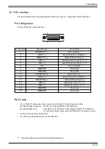
Pin Configuration
(Viewed from the connector face.)
RAS Cable
• Use a Dsub 15-pin socket-type connector and a Dsub 15-pin plug-type cable.
Recommended connector : Dsub 15-pin plug XM2A-1501 (Omron)
Recommended cover
: Standard cover for Dsub 15-pin plugs, XM2S-1513 (Omron)
If necessary, Omron jack screws XM2Z-0073 can also be used.
• Connect the FG cable to the shell.
• Use inch type attachment screws (#4-40UNC).
*1 General-purpose Input will latch Input Information.
8
1
15
9
Pin Number
Signal name
Description
1
ALARM-OUT (
−
)
Alarm Output (
−
)
2
DOUT (
−
)
General-purpose Output (
−
)
3
RESET-IN (
−
)
Remote Reset Input (
−
)
4
DIN0 (
−
)
General-purpose Input 0 (
−
) *1
5
DIN1 (
−
)
General-purpose Input 1 (
−
) *1
6
NC
No Connection
7
RESERVE
Reserved
8
RESERVE
Reserved
9
ALARM-OUT (+)
Alarm Output (+)
10
DOUT (+)
General-purpose Output (+)
11
RESET-IN (+)
Remote Reset Input (+)
12
DIN0 (+)
General-purpose 0 (+) *1
13
DIN1 (+)
General-purpose 1 (+) *1
14
RESERVE
Reserved
15
RESERVE
Reserved


