background image

Go-Go Elite Traveller Plus Technical Troubleshooting Guide

www.pridemobility.com

9

21. Remove the cover from the S-drive controller (7). See dia-

gram 3.

22. Unplug connector 5b from connector 7a. See diagram 2.
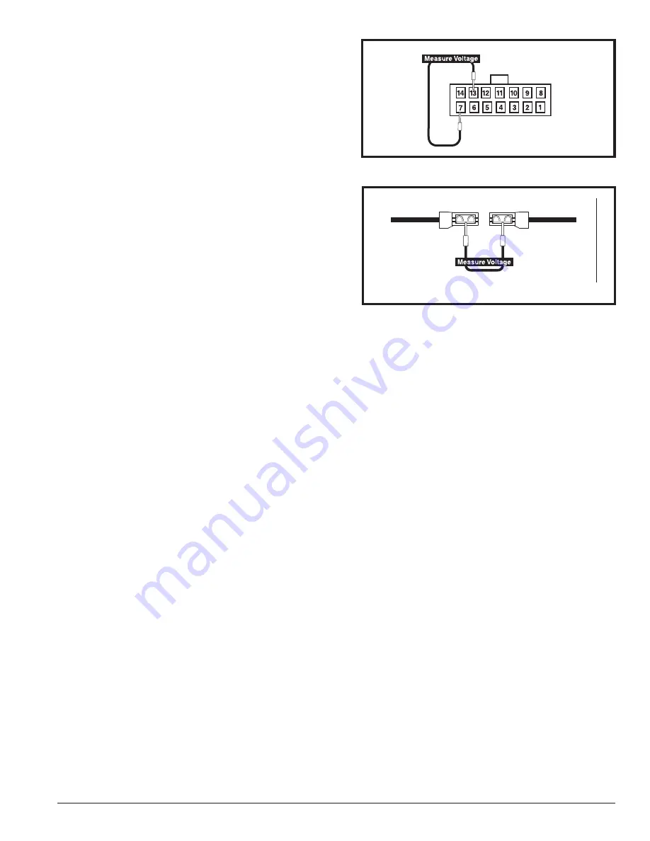
23. Measure voltage across pin 7 and pin 13 on connector 7a.

See figure 10.

— If your multimeter indicates 0VDC, then go to the

next step.

— If your multimeter indicates greater than 18VDC, then

replace the front-to-rear interface harness (5) and retest
the system

24. Unplug connectors 6b and 6c from connector 7e. See dia-

gram 2.

25. Measure voltage across connectors 6b and 6c.  See fig-

ure 11.

— If your multimeter indicates 0VDC, then replace the power

interface harness (6) and retest the system.

— If your multimeter indicates greater than 18VDC, then

replace the S-drive controller (7) and retest the system.

.

Figure 10. Connector 7a

6b

6c 

Figure 11. Connectors 6b and 6c

Содержание Go-Go Elite traveller

Страница 1: ......

Страница 2: ...ed Failure to perform mandatory actions can cause personal injury and or equipment damage On the product this icon is represented as a white symbol on a blue dot with a white border PROHIBITED These a...

Страница 3: ...EY SWITCH NO SIGNS OF POWER 6 SECTION 2 KEY INSERTED INTO THE KEY SWITCH POWER ON BUT SCOOTER DOES NOT MOVE 10 SECTION 3 BEEP CODE DIAGNOSIS 11 BEEP CODE 3 Battery Voltage is too High 11 BEEP CODE 5 B...

Страница 4: ...ealwitheachcodeforthatmodel Thetroubleshootingguideutilizesdiagramsthatarelocatedinthefrontandbackoftheguide Thesediagramsidentify main components by number 1 2 3 etc and all connectors by number with...

Страница 5: ...oubleshooting Key 3 2 1 1 5 6 7 8 9 10 4 12 11 1 2 3 4 5 6 7 8 9 10 11 12 BATTERY HARNESSES SPEED POT THROTTLE POT MOTOR INTERFACE HARNESS BRAKE HARNESS MOTOR TRANSAXLE ASSEMBLY CONTROLLER POWER INTER...

Страница 6: ...he system 4 Open the battery box See figure 2 _ WARNING Battery posts terminals and related accessories contain lead and lead compounds Wear goggles and gloves when handling batteries and wash hands a...

Страница 7: ...ttery box circuit breaker harness DWR9983H010 If your multimeter does not indicate less than 1 ohm for both measurements then replace both battery box circuit breaker harnesses 10 Remove fuse 5c See d...

Страница 8: ...18 Reinstall the battery box making sure connector 1h and connector 6a make contact See diagram 2 19 Unplug connector 5a from connector 4a See diagram 2 20 Measure voltage across pin 1 and pin 6 on c...

Страница 9: ...next step If your multimeter indicates greater than 18VDC then replace the front to rear interface harness 5 and retest the system 24 Unplug connectors 6b and 6c from connector 7e See dia gram 2 25 M...

Страница 10: ...o the powered on position measure resistance across pin 2 and pin 3 on connector 3a See figure 13 If your multimeter indicates less than 1 ohm then go to the next step If your multimeter indicates an...

Страница 11: ...tage to drop Do not allow the battery voltage to fall into the red area on the battery condition meter 2 Make sure the client is only using the off board charger supplied with the Go Go Elite Travelle...

Страница 12: ...l lever to the neutral center position Reinsert the key into the key switch and power up the scooter 2 Refer to BEEP CODE 7 Throttle Trip to determine if the throttle pot is faulty BEEP CODE 7 Throttl...

Страница 13: ...way to the tortoise position 11 Measure resistance across pin 1 and pin 2 on connector 12a See figure 22 If your multimeter indicates about 25k ohms then go to the next step If your multimeter indicat...

Страница 14: ...functioning properly Controller is not functioning properly Solution Use the following procedure to determine the source of the fault 1 Separate the front and rear halves of the scooter Refer to the...

Страница 15: ...s then replace the S Drive controller 7 and retest the system Figure 29 Motor Brake Transaxle Removal 8c 8d 8e 2 If the brake or drive system is dragging the scooter may drive for a period of time bef...

Страница 16: ...e pot or throttle control lever is not in the neutral position when turning the key switch on or that the throttle pot may be faulty Refer to BEEP CODE 6 Throttle Trip BEEP CODE 7 Throttle Trip Drive...

Страница 17: ...9975H001 DWR9984H003 DWR9983H006 HORN BUTTON THROTTLE POT KEY SWITCH SPEED POT VOLT METER 3A FUSE HORN DRVASMB1859 TRANSAXLE MOTOR BRAKE BATASMB1045 BATTERY BOX DWR9983H009 DWR9983H011 DWR9983H010 CIR...

Страница 18: ...c 7d 7e 7 1 2 3 4 5 6 7 8 9 10 11 12 BATTERY HARNESSES SHOWN ON DIAGRAM 2 SPEED POT THROTTLE POT MOTOR INTERFACE HARNESS BRAKE HARNESS MOTOR TRANSAXLE ASSEMBLY CONTROLLER POWER INTERFACE HARNESS FRONT...

Страница 19: ...Free Service Hotline 877 800 1248 DealersOnly Press 7 for Technical Service then Press 1 for Help Desk or Press 2 for Quantum Rehab Tech or Press 3 for Power Chair Tech or Press 4 for Scooter Tech or...

Отзывы: