Section 6: ELECTRICAL
PA1553
57
CAUTION
Never connect a voltmeter or V.O.M. to
measure bulb voltage as instrument will be
destroyed.
Troubleshooting and Safety
When switching on the Xenon headlamp using
the rocker switch, a lamp short-circuit test is
performed.
Current is detected in the lamp circuit before the
ignition time and ignition prevented. Connection
of the "hot" lamp to the body mass also prevents
ignition. In both cases, the system is cut off
within < 0.2 s and can only be restarted via the
rocker switch.
In general, the maximum ignition time is < 0.2 s,
which period is followed by cutoff. This would
happen if a lamp was defected.
Lamp missing: system is cut off after < 0.2 s.
If lamp components or cables are damaged by
force (accident) so that contact with hazardous
parts is possible, the current in these lines is
earthed by the vehicle body and - as with a
defective household appliance - switched off
when 30 mA are reached within < 0.2 s. the
cutoff time is shortened by a more powerful
defect current.
To protect the ballast, a counter in the electronic
safety system ensures that a defective lamp can
only be switched off 7 times consecutively after
a successful ignition, after which the device is
cut off. This prevents flutter and flashing. This
counter is put out of action when the lamp cutoff
time repetition interval is longer than 1.3 s so
that temporary non-defect disturbances that
result in immediate invisible re-ignition do not
cause lamp cutoff.
A warning notice on the lamp plug makes you
aware of the fact that the lamp is operated in this
system on a higher voltage (you should
therefore switch off the lamp before working on
this part).
After taking out the lamp, the contact pins are in
a practically idle state (< 34 Volt) after < 0.5
seconds so that there is no immediate danger of
electric shock even if the warning is
disregarded.
With this safety concept there is no danger to
check the ballast with a new bulb. There is a
very high probability that the ballast is OK if the
ballast can ignite the bulb.
One simple test to check the ballast would be to
measure the Nominal current of 1.58 A after one
minute for the 24V ballast.
12.2 STOP, TAIL, DIRECTIONAL, BACK-UP,
AND HAZARD WARNING LIGHTS
A combination stoplight, taillight, directional
signal light and back-up light assembly is
mounted at the rear, on each side of the vehicle.
Furthermore, when braking, two center
stoplights (LED) and a cyclops light (LED) will
illuminate simultaneously with the stoplights on
the sides for increased safety. The L.H. and
R.H. side center stop lights are also used as
directional signal and marker lights.
The stop, tail, directional signal and back-up
lights consist of individual LED lights mounted
on the engine rear door, and each light is
serviced individually as a complete unit. The
back-up light uses a regular tungsten bulb.
The hazard warning flashing system uses the
front, side and rear directional lights
simultaneously. This system is energized by a
switch on the L.H. dashboard.
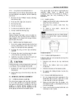
12.2.1 Lamp Removal and Replacement
1. Open engine compartment rear door.
2. Remove the lamp support retaining screws
(2), and then from the outside, remove the
lamp and its support.
3. From the outside, install the new lamp with
its support then fasten the retaining screws.
12.2.2 Center Stoplights and Cyclops Light
Removal and Replacement
These (LED) lights are sealed unit and should
be replaced as an assembly in accordance with
the following procedure:
1. Unscrew both “Phillips” light screws then
remove the light assembly.
2. Install new light assembly and secure using
screws.
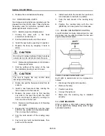
12.3 LICENSE PLATE LIGHT
Two LED units are mounted above the rear
license plate(s) of vehicle. In case of burn out,
the LED unit must be changed according to the
following procedure.
Содержание LE MIRAGE XLII
Страница 1: ...COACH MANUFACTURER MAINTENANCE MANUAL LE MIRAGE XLII BUS SHELLS PA1553 ...
Страница 2: ......
Страница 12: ...Section 00 GENERAL INFORMATION 10 PA1553 FIGURE 13 METRIC US STANDARD CONVERSION TABLE 00005 ...
Страница 13: ...Section 00 GENERAL INFORMATION PA1553 11 FIGURE 14 CONVERSION CHART 00006 ...
Страница 14: ......
Страница 30: ......
Страница 131: ...section01f tif 1700x2164x2tiff ...
Страница 132: ...section01f tif 1700x2164x2tiff 2 ...
Страница 133: ...section01f tif 1700x2164x2 3 ...
Страница 134: ...section01f tif 1700x2164x2 4 ...
Страница 135: ...section01f tif 1700x2164x2 5 ...
Страница 136: ...section01f tif 1700x2164x2 6 ...
Страница 137: ...section01f tif 1700x2164x2 7 ...
Страница 138: ...section01f tif 1700x2164x2 8 ...
Страница 139: ...section01f tif 1700x2164x2 9 ...
Страница 140: ...section01f tif 1700x2164x2tiff 10 ...
Страница 141: ...section01f tif 1700x2164x2tiff 11 ...
Страница 142: ...section01f tif 1700x2164x2tiff 12 ...
Страница 143: ...The ONLY Motor Coach Power Choice ...
Страница 182: ......
Страница 185: ...Section 04 EXHAUST SYSTEM PA1553 3 FIGURE 2 EXHAUST SYSTEM INSTALLATION W5 04013 ...
Страница 206: ......
Страница 207: ......
Страница 208: ......
Страница 209: ......
Страница 210: ......
Страница 211: ......
Страница 212: ......
Страница 213: ......
Страница 214: ......
Страница 278: ......
Страница 328: ......
Страница 345: ...FAULT CODE MANUAL Created on 00 04 25 15 30 1 FAULT CODE MANUAL B7L B7TL B12 ...
Страница 370: ......
Страница 397: ......
Страница 398: ......
Страница 399: ......
Страница 400: ......
Страница 401: ......
Страница 402: ......
Страница 403: ......
Страница 404: ......
Страница 405: ......
Страница 406: ......
Страница 407: ......
Страница 408: ......
Страница 419: ...SPICER SPECIALITY AXLE DIVISION place product photo here SERVICE MANUAL GENERAL INFORMATION NDS Axle range ...
Страница 425: ......
Страница 438: ...Page No 12 NDS2 issue A Spicer SpecialityAxle Division Technical Publications Spicer Speciality Axle Division ...
Страница 464: ...Page No 18 Manual No NDS8 Spicer Speciality Axle Division Technical Publications Spicer Speciality Axle Division TP1193 ...
Страница 492: ...Section 12 BRAKE AND AIR SYSTEM PA1553 20 FIGURE 38 AIR OPERATED BRAKING SYSTEM W0 WE ...
Страница 493: ...Section 12 BRAKE AND AIR SYSTEM PA1553 21 FIGURE 39 AIR OPERATED BRAKING SYSTEM W5 ...
Страница 500: ...Section 12 BRAKE AND AIR SYSTEM PA1553 28 FIGURE 46 ABS 4S 4M CONFIGURATION ...
Страница 528: ...16 BW2158 Honeywell Commercial Vehicle Systems Company 4 2001 Printed in USA ...
Страница 532: ......
Страница 540: ......
Страница 548: ......
Страница 555: ......
Страница 568: ......
Страница 588: ......
Страница 594: ......
Страница 597: ......
Страница 650: ...52 9 Inch Fraction Decimal and Millimeter Equivalents Chart Up to 1 inch 9 1 9 Conversion Tables ...
Страница 665: ......
Страница 666: ......
Страница 667: ......
Страница 668: ......
Страница 669: ......
Страница 670: ......
Страница 671: ......
Страница 672: ......
Страница 673: ......
Страница 674: ......
Страница 675: ......
Страница 676: ......
Страница 677: ......
Страница 678: ......
Страница 679: ......
Страница 680: ......
Страница 681: ......
Страница 682: ......
Страница 683: ......
Страница 684: ......
Страница 685: ......
Страница 686: ......
Страница 687: ......
Страница 688: ......
Страница 689: ......
Страница 690: ......
Страница 691: ......
Страница 692: ......
Страница 693: ......
Страница 694: ......
Страница 695: ......
Страница 696: ......
Страница 697: ......
Страница 698: ......
Страница 699: ......
Страница 700: ......
Страница 701: ......
Страница 702: ......
Страница 703: ......
Страница 704: ......
Страница 705: ......
Страница 706: ......
Страница 707: ......
Страница 708: ......
Страница 709: ......
Страница 710: ......
Страница 711: ......
Страница 712: ......
Страница 713: ......
Страница 714: ......
Страница 715: ......
Страница 716: ......
Страница 717: ......
Страница 718: ......
Страница 719: ......
Страница 720: ......
Страница 721: ......
Страница 722: ......
Страница 723: ......
Страница 724: ......
Страница 725: ......
Страница 726: ......
Страница 727: ......
Страница 728: ......
Страница 729: ......
Страница 730: ......
Страница 731: ......
Страница 732: ......
Страница 733: ......
Страница 734: ......
Страница 735: ......
Страница 736: ......
Страница 737: ......
Страница 738: ......
Страница 739: ......
Страница 740: ......
Страница 741: ......
Страница 742: ......
Страница 743: ......
Страница 744: ......
Страница 745: ......
Страница 746: ......
Страница 747: ......
Страница 748: ......
Страница 749: ......
Страница 750: ......
Страница 751: ......
Страница 752: ......
Страница 753: ......
Страница 754: ......
Страница 755: ......
Страница 756: ......
Страница 757: ......
Страница 758: ......
Страница 759: ......
Страница 760: ......
Страница 761: ......
Страница 762: ......
Страница 763: ......
Страница 764: ......
Страница 765: ......
Страница 766: ......
Страница 767: ......
Страница 768: ......
Страница 769: ......
Страница 770: ......
Страница 771: ......
Страница 772: ......
Страница 773: ......
Страница 774: ......
Страница 775: ......
Страница 776: ......
Страница 777: ......
Страница 778: ......
Страница 779: ......
Страница 780: ......
Страница 781: ......
Страница 782: ......
Страница 783: ......
Страница 784: ......
Страница 785: ......
Страница 786: ......
Страница 787: ......
Страница 788: ......
Страница 789: ......
Страница 790: ......
Страница 791: ......
Страница 792: ......
Страница 793: ......
Страница 794: ......
Страница 795: ......
Страница 796: ......
Страница 797: ......
Страница 798: ......
Страница 799: ......
Страница 800: ......
Страница 801: ......
Страница 802: ......
Страница 803: ......
Страница 804: ......
Страница 805: ......
Страница 806: ......
Страница 807: ......
Страница 808: ......
Страница 809: ......
Страница 810: ......
Страница 811: ......
Страница 812: ......
Страница 813: ......
Страница 814: ......
Страница 815: ......
Страница 816: ......
Страница 817: ......
Страница 818: ......
Страница 819: ......
Страница 820: ......
Страница 821: ......
Страница 822: ......
Страница 844: ...Section 16 SUSPENSION PA1553 22 FIGURE 26 SWAY BAR FRONT SUSPENSION 16138D FIGURE 27 SWAY BAR REAR SUSPENSION 16014 ...
Страница 964: ......
Страница 978: ......
Страница 980: ......
Страница 982: ......
Страница 988: ......
Страница 994: ......
Страница 998: ......
Страница 1002: ......
Страница 1004: ...PROCEDURE NO PR00044 REVISION 00 Page 2 of 2 Slide out ...
Страница 1008: ......
Страница 1010: ......
Страница 1012: ......
Страница 1018: ......
Страница 1022: ......
Страница 1024: ......
Страница 1032: ......
Страница 1054: ......
Страница 1066: ......
Страница 1070: ......
Страница 1074: ......
Страница 1110: ......
Страница 1116: ......
Страница 1122: ......
Страница 1142: ......
Страница 1162: ...Section 22 HEATING AND AIR CONDITIONING PA1553 16 FIGURE 16 REFRIGERANT CIRCUIT CENTRAL SYSTEM 22247 ...
Страница 1165: ...Section 22 HEATING AND AIR CONDITIONING PA1553 19 FIGURE 17 DOUBLE SWEEP EVACUATION SET UP ...
Страница 1186: ...Section 22 HEATING AND AIR CONDITIONING PA1553 40 FIGURE 42 REFRIGERANT CIRCUIT SMALL SYSTEM 22336 ...
Страница 1191: ...Section 22 HEATING AND AIR CONDITIONING PA1553 45 FIGURE 50 CENTRAL HEATING SYSTEM COMPONENTS 22338 ...
Страница 1201: ...Section 22 HEATING AND AIR CONDITIONING PA1553 55 FIGURE 64 HEATER LINE SHUTOFF VALVES WE W0 ...
Страница 1202: ...Section 22 HEATING AND AIR CONDITIONING PA1553 56 FIGURE 65 SMALL HEATING SYSTEM COMPONENTS 22337 ...
Страница 1208: ......
Страница 1209: ...Compressor 62 11052 Rev A WORKSHOP MANUAL for MODEL 05G TWIN PORT COMPRESSOR R ...
Страница 1210: ...WORKSHOP MANUAL COMPRESSOR MODEL 05G TWIN PORT ...
Страница 1233: ...Compressor 62 11053 Rev B SERVICE PARTS LIST for MODEL 05G TWIN PORT COMPRESSOR 1 2 3 4 5 6 R ...
Страница 1261: ......
Страница 1262: ......
Страница 1263: ...1 ...
Страница 1264: ...2 ...
Страница 1265: ...3 ...
Страница 1266: ...4 ...
Страница 1267: ...5 ...
Страница 1268: ...6 ...
Страница 1269: ...7 ...
Страница 1270: ...8 ...
Страница 1271: ...9 ...
Страница 1272: ......
Страница 1287: ...Section 24 LUBRICATION PA1553 5 FIGURE 2 LUBRICATION AND SERVICING POINTS ON INDEPENDENT FRONT SUSPENSION VEHICLES 24036 ...
Страница 1294: ......
Страница 1305: ...Section 26 XLII SLIDE OUT PA1553 11 ...
Страница 1306: ...Section 26 XLII SLIDE OUT PA1553 12 FIGURE 16 KEYLESS BUSHING INSTALLATION INSTRUCTION ...


