Section 22: HEATING AND AIR CONDITIONING
PA1553
30
sleeve in the bonnet enters the mating hole
in the body.
4. Insert the four socket head screws and
tighten evenly.
5. Replace the coil as stated previously.
6. Add a small quantity of refrigerant R-134a to
the low side of the system. Check for leaks.
Return the system to normal operation.
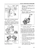
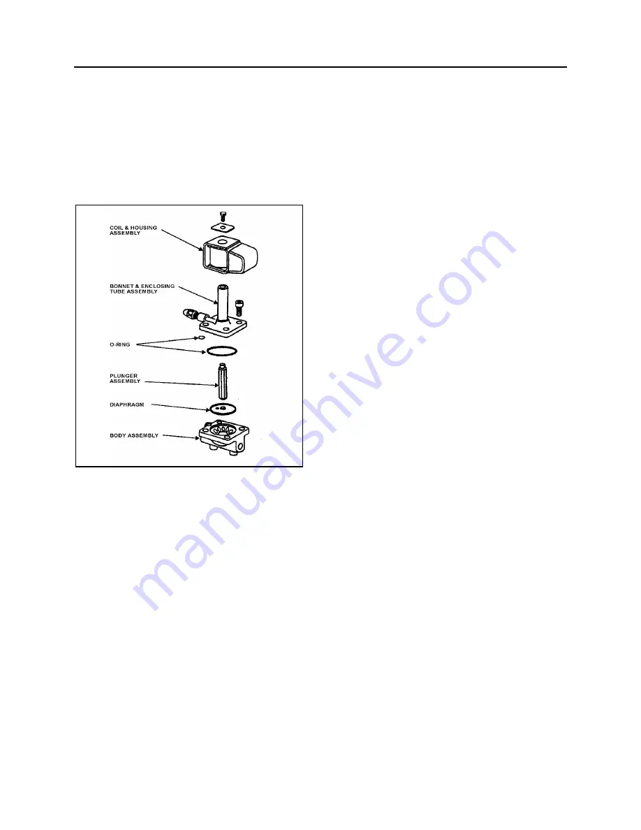
FIGURE 33: REFRIGERANT SOLENOID VALVE
22044
9.8 EXPANSION
VALVE
9.8.1 Cabin HVAC Unit
The expansion valve for the cabin HVAC unit is
a thermo-sensitive valve with a remote control
bulb head attached to the evaporator outlet line
and is accessible by the cabin air filters access
door (Fig. 15 & 16). The valve regulates the flow
of refrigerant liquid into the evaporator coils and
is controlled by the suction gas temperature
leaving the evaporator. The bulb head senses
the refrigerant gas temperature as it leaves the
evaporator. High temperature will cause
expansion and pressure on the power head and
spring. Such action causes the assembly valve
to open, allowing a flow of refrigerant liquid into
the evaporator.
The remote bulb and power assembly is a
closed system. The pressure within the remote
bulb and power assembly corresponds to the
saturation pressure of the refrigerant
temperature leaving the evaporator and moves
the valve pin in the opening direction. Opposed
to this force, on the under side of the diaphragm
and acting in the closing direction, is the force
exerted by the superheat spring. As the
temperature of the refrigerant gas at the
evaporator outlet increases above the saturation
temperature corresponding to the evaporator
pressure, it becomes superheated. The
pressure thus generated in the remote bulb and
power assembly surpasses the combined
pressures of the evaporator pressure and the
superheat spring, causing the valve pin to move
in the opening direction. Conversely, as the
temperature of the
refrigerant
gas leaving the
evaporator decreases, the pressure in the
remote bulb and power assembly also
decreases and the combined evaporator and
spring pressures cause the valve pin to move in
the closing position.
As the operating superheat is raised, the
evaporator capacity decreases, since more of
the evaporator surface is required to produce
the superheat necessary to open the valve. It is
obvious, then, that it is most important to adjust
the operating superheat correctly and that a
minimum change in superheat to move the valve
pin to full open position, is of vital importance
because it provides savings in both initial
evaporator cost of operation. Accurate and
sensitive control of the refrigerant liquid flowing
to the evaporator is necessary to provide
maximum evaporator capacity under load
conditions. The spring is adjusted to give 12 to
16
o
F (-11.1 to -8.8
o
C) of superheat at the
evaporator outlet.
This ensures that the refrigerant leaving the
evaporator is in a completely gaseous state
when drawn into the suction side of the
compressor. Liquid would damage the
compressor valve, piston and heads if allowed
to return in the suction line.
A vapor is said to be superheated when its
temperature is higher than the saturation
temperature corresponding to its pressure. The
amount of the superheat is, of course, the
temperature increase above the saturation
temperature at the existing pressure.
As the refrigerant moves along in the
evaporator, the liquid boils off into a vapor and
the amount of liquid decreases until all the liquid
has evaporated due to the absorption of a
quantity of heat from the surrounding
atmosphere equal to the latent heat of
Содержание LE MIRAGE XLII
Страница 1: ...COACH MANUFACTURER MAINTENANCE MANUAL LE MIRAGE XLII BUS SHELLS PA1553 ...
Страница 2: ......
Страница 12: ...Section 00 GENERAL INFORMATION 10 PA1553 FIGURE 13 METRIC US STANDARD CONVERSION TABLE 00005 ...
Страница 13: ...Section 00 GENERAL INFORMATION PA1553 11 FIGURE 14 CONVERSION CHART 00006 ...
Страница 14: ......
Страница 30: ......
Страница 131: ...section01f tif 1700x2164x2tiff ...
Страница 132: ...section01f tif 1700x2164x2tiff 2 ...
Страница 133: ...section01f tif 1700x2164x2 3 ...
Страница 134: ...section01f tif 1700x2164x2 4 ...
Страница 135: ...section01f tif 1700x2164x2 5 ...
Страница 136: ...section01f tif 1700x2164x2 6 ...
Страница 137: ...section01f tif 1700x2164x2 7 ...
Страница 138: ...section01f tif 1700x2164x2 8 ...
Страница 139: ...section01f tif 1700x2164x2 9 ...
Страница 140: ...section01f tif 1700x2164x2tiff 10 ...
Страница 141: ...section01f tif 1700x2164x2tiff 11 ...
Страница 142: ...section01f tif 1700x2164x2tiff 12 ...
Страница 143: ...The ONLY Motor Coach Power Choice ...
Страница 182: ......
Страница 185: ...Section 04 EXHAUST SYSTEM PA1553 3 FIGURE 2 EXHAUST SYSTEM INSTALLATION W5 04013 ...
Страница 206: ......
Страница 207: ......
Страница 208: ......
Страница 209: ......
Страница 210: ......
Страница 211: ......
Страница 212: ......
Страница 213: ......
Страница 214: ......
Страница 278: ......
Страница 328: ......
Страница 345: ...FAULT CODE MANUAL Created on 00 04 25 15 30 1 FAULT CODE MANUAL B7L B7TL B12 ...
Страница 370: ......
Страница 397: ......
Страница 398: ......
Страница 399: ......
Страница 400: ......
Страница 401: ......
Страница 402: ......
Страница 403: ......
Страница 404: ......
Страница 405: ......
Страница 406: ......
Страница 407: ......
Страница 408: ......
Страница 419: ...SPICER SPECIALITY AXLE DIVISION place product photo here SERVICE MANUAL GENERAL INFORMATION NDS Axle range ...
Страница 425: ......
Страница 438: ...Page No 12 NDS2 issue A Spicer SpecialityAxle Division Technical Publications Spicer Speciality Axle Division ...
Страница 464: ...Page No 18 Manual No NDS8 Spicer Speciality Axle Division Technical Publications Spicer Speciality Axle Division TP1193 ...
Страница 492: ...Section 12 BRAKE AND AIR SYSTEM PA1553 20 FIGURE 38 AIR OPERATED BRAKING SYSTEM W0 WE ...
Страница 493: ...Section 12 BRAKE AND AIR SYSTEM PA1553 21 FIGURE 39 AIR OPERATED BRAKING SYSTEM W5 ...
Страница 500: ...Section 12 BRAKE AND AIR SYSTEM PA1553 28 FIGURE 46 ABS 4S 4M CONFIGURATION ...
Страница 528: ...16 BW2158 Honeywell Commercial Vehicle Systems Company 4 2001 Printed in USA ...
Страница 532: ......
Страница 540: ......
Страница 548: ......
Страница 555: ......
Страница 568: ......
Страница 588: ......
Страница 594: ......
Страница 597: ......
Страница 650: ...52 9 Inch Fraction Decimal and Millimeter Equivalents Chart Up to 1 inch 9 1 9 Conversion Tables ...
Страница 665: ......
Страница 666: ......
Страница 667: ......
Страница 668: ......
Страница 669: ......
Страница 670: ......
Страница 671: ......
Страница 672: ......
Страница 673: ......
Страница 674: ......
Страница 675: ......
Страница 676: ......
Страница 677: ......
Страница 678: ......
Страница 679: ......
Страница 680: ......
Страница 681: ......
Страница 682: ......
Страница 683: ......
Страница 684: ......
Страница 685: ......
Страница 686: ......
Страница 687: ......
Страница 688: ......
Страница 689: ......
Страница 690: ......
Страница 691: ......
Страница 692: ......
Страница 693: ......
Страница 694: ......
Страница 695: ......
Страница 696: ......
Страница 697: ......
Страница 698: ......
Страница 699: ......
Страница 700: ......
Страница 701: ......
Страница 702: ......
Страница 703: ......
Страница 704: ......
Страница 705: ......
Страница 706: ......
Страница 707: ......
Страница 708: ......
Страница 709: ......
Страница 710: ......
Страница 711: ......
Страница 712: ......
Страница 713: ......
Страница 714: ......
Страница 715: ......
Страница 716: ......
Страница 717: ......
Страница 718: ......
Страница 719: ......
Страница 720: ......
Страница 721: ......
Страница 722: ......
Страница 723: ......
Страница 724: ......
Страница 725: ......
Страница 726: ......
Страница 727: ......
Страница 728: ......
Страница 729: ......
Страница 730: ......
Страница 731: ......
Страница 732: ......
Страница 733: ......
Страница 734: ......
Страница 735: ......
Страница 736: ......
Страница 737: ......
Страница 738: ......
Страница 739: ......
Страница 740: ......
Страница 741: ......
Страница 742: ......
Страница 743: ......
Страница 744: ......
Страница 745: ......
Страница 746: ......
Страница 747: ......
Страница 748: ......
Страница 749: ......
Страница 750: ......
Страница 751: ......
Страница 752: ......
Страница 753: ......
Страница 754: ......
Страница 755: ......
Страница 756: ......
Страница 757: ......
Страница 758: ......
Страница 759: ......
Страница 760: ......
Страница 761: ......
Страница 762: ......
Страница 763: ......
Страница 764: ......
Страница 765: ......
Страница 766: ......
Страница 767: ......
Страница 768: ......
Страница 769: ......
Страница 770: ......
Страница 771: ......
Страница 772: ......
Страница 773: ......
Страница 774: ......
Страница 775: ......
Страница 776: ......
Страница 777: ......
Страница 778: ......
Страница 779: ......
Страница 780: ......
Страница 781: ......
Страница 782: ......
Страница 783: ......
Страница 784: ......
Страница 785: ......
Страница 786: ......
Страница 787: ......
Страница 788: ......
Страница 789: ......
Страница 790: ......
Страница 791: ......
Страница 792: ......
Страница 793: ......
Страница 794: ......
Страница 795: ......
Страница 796: ......
Страница 797: ......
Страница 798: ......
Страница 799: ......
Страница 800: ......
Страница 801: ......
Страница 802: ......
Страница 803: ......
Страница 804: ......
Страница 805: ......
Страница 806: ......
Страница 807: ......
Страница 808: ......
Страница 809: ......
Страница 810: ......
Страница 811: ......
Страница 812: ......
Страница 813: ......
Страница 814: ......
Страница 815: ......
Страница 816: ......
Страница 817: ......
Страница 818: ......
Страница 819: ......
Страница 820: ......
Страница 821: ......
Страница 822: ......
Страница 844: ...Section 16 SUSPENSION PA1553 22 FIGURE 26 SWAY BAR FRONT SUSPENSION 16138D FIGURE 27 SWAY BAR REAR SUSPENSION 16014 ...
Страница 964: ......
Страница 978: ......
Страница 980: ......
Страница 982: ......
Страница 988: ......
Страница 994: ......
Страница 998: ......
Страница 1002: ......
Страница 1004: ...PROCEDURE NO PR00044 REVISION 00 Page 2 of 2 Slide out ...
Страница 1008: ......
Страница 1010: ......
Страница 1012: ......
Страница 1018: ......
Страница 1022: ......
Страница 1024: ......
Страница 1032: ......
Страница 1054: ......
Страница 1066: ......
Страница 1070: ......
Страница 1074: ......
Страница 1110: ......
Страница 1116: ......
Страница 1122: ......
Страница 1142: ......
Страница 1162: ...Section 22 HEATING AND AIR CONDITIONING PA1553 16 FIGURE 16 REFRIGERANT CIRCUIT CENTRAL SYSTEM 22247 ...
Страница 1165: ...Section 22 HEATING AND AIR CONDITIONING PA1553 19 FIGURE 17 DOUBLE SWEEP EVACUATION SET UP ...
Страница 1186: ...Section 22 HEATING AND AIR CONDITIONING PA1553 40 FIGURE 42 REFRIGERANT CIRCUIT SMALL SYSTEM 22336 ...
Страница 1191: ...Section 22 HEATING AND AIR CONDITIONING PA1553 45 FIGURE 50 CENTRAL HEATING SYSTEM COMPONENTS 22338 ...
Страница 1201: ...Section 22 HEATING AND AIR CONDITIONING PA1553 55 FIGURE 64 HEATER LINE SHUTOFF VALVES WE W0 ...
Страница 1202: ...Section 22 HEATING AND AIR CONDITIONING PA1553 56 FIGURE 65 SMALL HEATING SYSTEM COMPONENTS 22337 ...
Страница 1208: ......
Страница 1209: ...Compressor 62 11052 Rev A WORKSHOP MANUAL for MODEL 05G TWIN PORT COMPRESSOR R ...
Страница 1210: ...WORKSHOP MANUAL COMPRESSOR MODEL 05G TWIN PORT ...
Страница 1233: ...Compressor 62 11053 Rev B SERVICE PARTS LIST for MODEL 05G TWIN PORT COMPRESSOR 1 2 3 4 5 6 R ...
Страница 1261: ......
Страница 1262: ......
Страница 1263: ...1 ...
Страница 1264: ...2 ...
Страница 1265: ...3 ...
Страница 1266: ...4 ...
Страница 1267: ...5 ...
Страница 1268: ...6 ...
Страница 1269: ...7 ...
Страница 1270: ...8 ...
Страница 1271: ...9 ...
Страница 1272: ......
Страница 1287: ...Section 24 LUBRICATION PA1553 5 FIGURE 2 LUBRICATION AND SERVICING POINTS ON INDEPENDENT FRONT SUSPENSION VEHICLES 24036 ...
Страница 1294: ......
Страница 1305: ...Section 26 XLII SLIDE OUT PA1553 11 ...
Страница 1306: ...Section 26 XLII SLIDE OUT PA1553 12 FIGURE 16 KEYLESS BUSHING INSTALLATION INSTRUCTION ...


