128-9302
14 of 28
14
Factory Lock Relay
Factory Unlock Relay
87a
87
30
85
86
87a
87
30
86
85
From Fuse Box + 12 Volts
Lock
Unlock
To Red Lock Wire
Of Control Module
To Green Unlock Wire
Of Control Module
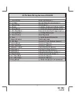
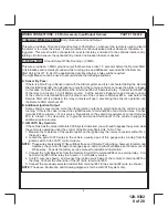
3 Pin Door Lock/Unlock Harness:
(White Connector) 300mA
Part # 1122906
1 Red Wire:
(-) Lock
The Red wire provides a (-) Negative Pulse when the transmitter is used to lock the doors.
2 Green:
(-) Unlock
The Green wire provides a (-) Negative Pulse when the transmitter is used to unlock the doors.
3 Red/Black:
(-) Second Unlock
The Red w/Black trace wire will provide a (-) Negative Pulse when the transmitter unlock button is pressed
a second time directly following a first unlock if the feature is selected at time of installation. This feature
is used for second step unlock, (all doors unlock), in a two step unlock circuit. In this arrangement, Red
is used to control the drivers door unlock relay, and the Red/Black will be used to control the unlocking
of all other doors.
3 Wire Ground Switched Door Lock Circuits:
In this application, the Red wire of the door lock harness provides a ground pulse during the arming se-
quence, or pulsed ground lock output. Connect the Red wire to the low current ground signal wire from
the factory door lock switch to the factory door lock relay.
The Green wire of the door lock harness provides a ground pulse during the disarming sequence, or
pulsed ground unlock output. Connect the Green wire to the low current ground signal wire from the
factory door unlock switch to the factory door unlock relay. See the following diagram for Wiring Detail.
3 Wire Ground Switched Door Lock/Unlock Wiring Detail
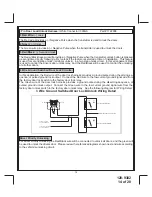
Driver Priority Unlocking:
For driver Priority Unlocking the Red/Black wire will be connected to unlock all doors, and the green will
be used to unlock the drivers door. Please review the reference diagrams shown next and wire according
to the vehicle's unlocking circuit.
Содержание APS-687E
Страница 27: ...128 9302 27 of 28 27 NOTES...


