128-9302
9 of 28
9
87a
87
30
85
86
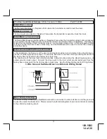
To LT Blue, (GWR) Wire
From Multi Pin Harness
To Fused + 12 Volt Battery Source
VATS Control Module
VAT Wire #1
VAT Wire #2
Cut Factory Wire
and route through
relay as shown
X
Matching
Resistor
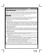
3 Black w/ White trace Wire:
300 mA Horn Output
The black w/ white trace wire is provided to beep the vehicle’s horn. This is a transistorized low current
output, and should only be connected to the low current ground output from the vehicle’s horn switch.
If the vehicle uses a + 12 VDC horn switch, then connect the black w/ white trace
wire to terminal 86 of a 30Amp automotive relay, and connect relay terminal 85 to a fused
+ 12 VDC battery source. Connect relay terminal 87 to the vehicle’s horn switch output, and connect relay
terminal 30 to a fused + 12 VDC battery source.
4
Brown Wire:
(+) Inhibit Shut Down
Any time + 12 Volts is applied to the Brown wire, the Remote Starter will be prevented from operating,
even if the signal is received from the transmitter. If there is a neutral start wire in the vehicle that switches
+ 12 volts when the vehicle is in any gear other than Park or Neutral, this wire can be connected to that
vehicle wire to prevent starting while in gear.
5 Brown w/ Black trace Wire:
Positive Inhibit Input
The Brown w/ Black Trace wire provides an instant shutdown for the Remote Start Control module when-
ever it gets + 12 volts. If the Brake lights switch in the vehicle sw 12 volts to the brake light circuit,
connect the Brown w/ Black trace wire to the output side of the brake switch. This will allow the Remote
Start to shut down if an attempt is made to operate the vehicle without the key while running under the
control of the Remote Start. In most vehicles, in order to shift into gear, the brake pedal must be depressed.
The brake input will in turn cause the remote start unit to shut off.
6 DK. Blue w/ Black trace Wire:
External Trigger Input
The Dark Blue/Black trace wire allows the remote start unit to be activated from an external source. The
intent of this wire is to allow the unit to be controlled from a "Car Connection" / or "CAR-LINK" paging
system or similar device. When this wire receives a ground pulse, the unit will start the vehicle. Connect
this wire to a ground pulsed output from the controlling circuit.
7 Orange w/ Black trace Wire:
(-) Parking Brake Input
This wire is used only when the turbo timer mode, Bank 3, feature # 16 is selected ON. This input insures
that the vehicle parking brake is applied whenever the vehicle is set up for and the turbo timer circuit is
used. This input must switch to ground when the vehicle's parking brake is applied. Connect the Orange/
Black wire to the negative output of the vehicle's parking brake switch.
8 Green w/ Yellow trace Wire:
Diesel Wait To Start Input
The green/yellow wire, when connected to the wire that get + 12 volts during the glow plug preheat
Содержание APS-687E
Страница 27: ...128 9302 27 of 28 27 NOTES...


