background image

4

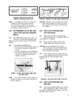
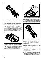
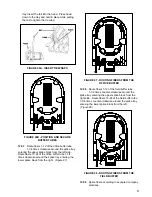
FIGURE 7 - END PLATE SHOWING THE

DESIGNATED DRILL MARKS

5.02

To enable bonding/strain relief brackets to be
properly applied, the cable holes must be

drilled at the designated drill marks highlighted in
yellow.

5.03

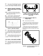
To position End Plate in the cutter:

— Rotate End Plate and slide bearing block

along the guides until the drill is positioned over
designated drill marks.

— Then, tighten the clamp screw and

thumbscrew on the bearing block. (Figure 8).

FIGURE 8 - BLADE POSITION

CAUTION:

A small nylon pellet backs up the

thumbscrews in the bearing block.  Using
cutter with pellet missing could cause damage
to the guide rails.

To prevent damage, remove the thumbscrews and
insert a small piece of cable sheath.  Additional nylon
pellets are available from PLP®.

5.04

Mount a 3/8" drill, drill blade adapter, and one

1/2" deep well socket to the upper end of the bearing
block shaft.

PLP TIP:

A special drill motor is available from

Preformed Line Products.  No matter what type
of electric drill you use, be sure to press down on

the body of the drill so that pressure is not
exerted sideways on the shaft.  This will result in
a much longer life of the bearing blocks.  Drill
through the End Plate slowly.

5.05

When using blades E-DD in the drill adapter,
cut through the black plastic of the End Plate

until foam is just visible in the outer ring. (Figure 9)
Use a screwdriver to pop out the plastic disk (not
necessary for A-D drill bits). (Figure 10)

FIGURE 9 - CUTTING THROUGH PLASTIC SHELL

FIGURE 10 - REMOVING PLASTIC DISK

5.06

Drill through the End Plate until the shaft
bottoms out on the stop collar.   When the

drill has bottomed out, stop the drill.

CAUTION:

Never bring the blade back up through

End Plate while it is still turning.  This could
result in an oversized hole.  Do not exert
sideways pressure on drill shaft, it may cause
damage to the bearing block.

5.07

If additional holes are needed, repeat
preceding steps 5.03 - 5.06. (Figure 11)

Содержание Coyote HiCount

Страница 1: ...ES FOR FIELD DRILLED END PLATES 5 6 8 END PLATE ASSEMBLY 6 7 9 BONDING AND OR GROUNDING CABLES WITH METALLIC COMPONENTS 7 CONTENTS PAGE Be sure to read and completely understand this procedure before...

Страница 2: ...s Common screwdriver 1 2 deep well socket 3 8 nutdriver or socket Needlenose pliers Buffer tube removal tool and or slitter Sidecutters Torque Wrench inch pound readings Power End Plate Cutter Availab...

Страница 3: ...easure each cable at the area where the End Plate is to be placed 4 00 END PLATE PREPARATION CUTTER SET UP 4 01 When using blades A D install the blade directly into the chuck For blades E DD first in...

Страница 4: ...ck shaft PLP TIP A special drill motor is available from Preformed Line Products No matter what type of electric drill you use be sure to press down on the body of the drill so that pressure is not ex...

Страница 5: ...m a LOCK TAPE Sealant strip to dry and remove excess C Cement applied to End Plate Figure 13 FIGURE 13 C CEMENT ON END PLATE 6 04 Without stretching apply LOCK TAPE Sealant over prepared surface of th...

Страница 6: ...END PLATE ASSEMBLY 8 01 Using the hex bolts provided fasten the L bracket and retaining clip to the End Plate 8 02 Before installing prepared cables into End Plate halves apply 1 4 6 35 mm wide bead...

Страница 7: ...et through the slot pro vided 9 03 If cable contains a strength member insert the strength member into the retainer clip and tighten Cut off excess strength member 10 00 INSTALL ORGANIZER ASSEMBLY 10...

Страница 8: ...MOVE SPLICE TRAY COVER 12 03 Position the back splice tray on the Splice Tray Rack and route the buffer tubes into the LEFT corner of the splice tray Mark the buffer tubes just beyond the tie down hol...

Страница 9: ...ERS FROM THE FIELD BUFFER 12 09 Splice fibers according to accepted company practices tray Insert the tail into the head Press head down to the tray and hold in place while pulling the tail to tighten...

Страница 10: ...First Then Finally Hand Tighten in Sequence with Ratchet All 1 Bolts First Followed by all 2 Bolts and so on Torque Each Bolt Following the Sequence to 125 in lbs 14 N m 90 in lbs 10 N m for 4 Closur...

Страница 11: ...and grounding harness of the manhole Securely tighten all connections 16 03 For direct buried installations extend a length of bonding ribbon not supplied from one of the threaded inserts to a ground...

Страница 12: ...uct is intended for use by trained craftspeople only This product SHOULD NOT BE USED by anyone who is not familiar with and trained in the use of it 18 04 When working in the area of energized lines w...

Отзывы: