background image

b. If the distance is NOT within the specified limit, continue procedure and calibrate

the lift motor assembly.

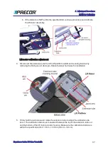
Lift motor calibration adjustment

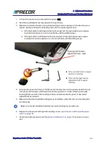
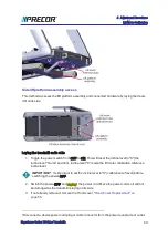
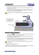
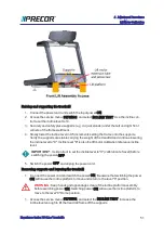
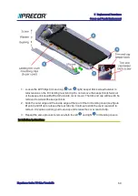
4. Disconnect the extension tube from the lift platform weldment mounting bracket by

removing the hitch pin and clevis pin. Retain fastener hardware for installation.

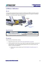
5. Firmly hold the jackscrew and rotate the extension tube to adjust the calibration dis-

tance. The calibration distance is measured between the top of the extension tube nut
and the bottom of the lift motor actuator housing. Make sure the calibration distance is
within the specification limit 1 1/8 in - 1 3/16 in (2.8 cm - 3.0 cm).

Experience Series 700 Line Treadmills

47

4 Adjustment Procedures

Lift Motor Calibration

Содержание Experience TRM700-16

Страница 1: ...Service Manual Experience Series 700 line TRM700 16 Base Treadmill 120 VAC and 240 VAC ...

Страница 2: ...acing Requirement 11 Safety Guidelines 13 Safety guideline you need to know and follow 13 2 Operation Verification 15 Operation Verification Tests 15 Error Code Verification Test 15 Hardware Validation Diagnostic Tests 15 Operational Tests 16 Tracking Test 16 Return to service 16 3 Standard Service Modes 17 About 17 Service Access Codes 17 How to Access the Service Software 18 P10 and P30 Series C...

Страница 3: ...ies Console 26 About menu 26 Equipment Usage menu 27 System Settings menu 28 Maintenance menu 31 Information Display 65 33 P10 P20 and P30 Series Consoles 33 P62 P80 and P82 Series Consoles 34 4 Adjustment Procedures 35 Available Adjustment Procedures 35 Drive Belt Tension and Alignment Adjustment 36 About 36 Procedure 36 Running Belt Tension and Tracking Adjustment 40 About 40 Tools 40 Specificat...

Страница 4: ... Replacement 62 Trim Side Cover Replacement 64 Dash Back Cover Replacement 66 Dash Front Cover Replacement 67 Dash Top and Bottom Cover Replacement 68 Side Arm Upper Lower Covers Replacement 72 Power Cord Replacement 73 About 73 Procedure 73 ON OFF SW Circuit Breaker Replacement 75 About 75 75 Wire Diagram 76 Procedure 76 ASL PCA Replacement 79 About 79 Wire Diagram 79 Procedure 80 E Stop Emergenc...

Страница 5: ...Motor Replacement 101 About 101 Procedure 101 Drive Roller Replacement 107 About 107 Procedure 107 Take up Roller Replacement 112 About 112 Procedure 112 Belt and Deck Replacement Procedure 116 About 116 Procedure 116 Lift Motor Replacement 122 About 122 Specification 122 Procedure 122 Lift Platform Replacement 131 About 131 Procedure 131 6 Troubleshooting 137 Experience Series 700 Line Treadmills...

Страница 6: ...A Event Log 145 Using the Error Log CPA Event Log 146 Active Status Light ASL 147 About 147 ASL Overview 148 ASL States 149 Setting the ASL light brightness level 149 Disabling the ASL Maintenance Reminder 150 Viewing the current ASL state 150 Viewing the ASL maintenance counter remaining miles or hours 150 Clearing the Blue Pulsing ASL State Maintenance Counter reset 151 Clearing the Yellow Yello...

Страница 7: ...iagram 161 System Overview Wire Diagram 161 Power Entry Assemble Wire Diagram 162 COMM Cable Wire Diagram 163 Console Wire Diagram 164 8 Parts Exploded View 166 About 166 Exploded View Diagram 166 Parts List 173 Appendix A Edition Information i Edition i Copyright i Appendix B Notices and Safety ii Trademarks ii Intellectual Property ii Warranty ii Safety Instruction ii Safety Notices ii Experienc...

Страница 8: ...treadmill Model TRM700 16 Base Configuration TRM731 TRM700 base 0 5 12 mph 0 15 incline with P30 console TRM761 TRM700 base 0 5 12 mph 0 15 incline with P62 console TRM781 TRM700 base 0 5 12 mph 0 15 incline with P82 console Separate Base Console Service Manuals There are separate service manuals for the machnine base and consoles Use this service manual to service repair and maintain the machine ...

Страница 9: ...ety Guidelines on page 13 Operation Verification on page 15 Standard Service Modes on page 17 Preventive Maintenance on page 152 Adjustment Procedures on page 35 Troubleshooting on page 137 Experience Series 700 Line Treadmills 2 1 Introduction ...

Страница 10: ...ine Console Feature Level TRM treadmill EFX elliptical 8 Experience Premium 8 P80 P82 7 EFX Fixed Ramp Moving Arms AMT AMT UBK Upright RBK Recumbent 7 Experience 6 P62 5 TRM High Speed Decline AMT Moving Step Height EFX Moving Ramp Moving Arms 6 Assurance Standard 3 P30 3 TRM No Decline AMT Fixed Step Height EFX Moving Ramp Fixed Arms 4 Precision Consumer 2 P20 1 EFX Fixed ramp Moving Arms 2 Energ...

Страница 11: ...rial number label may be wrong if the hood was incorrectly replaced with a different tread mill hood the serial number for that unit will be wrong Orientation The equipment orientation front right left back is referenced to an exerciser standing on the machine facing the console Experience Series 700 Line Treadmills 4 1 Introduction General Information ...

Страница 12: ...overs and Panels Equipment cover and access panel locations For cover removal and installation see Covers and Panels Replacement on page 54 Tools Experience Series 700 Line Treadmills 5 1 Introduction General Information ...

Страница 13: ...PN PPP000000020045101 12 wonder bar ESD safe vacuum cleaner ESD wrist strap Supplies Super Lube Gel with Telfon by Permatex Cleaning rags Mobil 1 NLGI 2 Teflon Synthetic Grease Cleaner Degreaser Simple Green Loctite 243 Blue Medium Strength Thread locker Cable ties 1 3 4 3 4 lengths Specification Summary Table This table provides a summary of system component torque and belt rating specifications ...

Страница 14: ...than the grade of the bolt Count the lines add two and you can determine the grade of the bolt In the case of a metric bolt the head will have a numerical marking to indicate the grade CAUTION Always replace bolts with the same grade If you don t know the grade of the replacement bolt DO NOT USE Parts IMPORTANT Always purchase OEM replacement parts and hardware from Precor If you use parts not app...

Страница 15: ... cleaners or solvents may void the TRM warranty l Mobil 1 NLGI 2 Teflon Synthetic Grease l Super Lube Gel with Telfon by Per matex CAUTION Do not apply any lubricants or wax to the deck and belt Do not use Wax Blast silicon sprays or other applied lubricants The use of these lubricants will quickly degrade the low friction surface of the deck CAUTION Do not use petroleum based lubricants on mechan...

Страница 16: ...dividual branch circuit provides a hot conductor and neutral conductor to a receptacle The conductors must not be looped daisy chained or connected to any other conductors or receptacles The circuit must be grounded according to NEC guidelines or local region electric codes CAUTION NEC National Electric Code guidelines or local region electric codes must be complied with Input Power Nominal 120 VA...

Страница 17: ...onnection is required Using a 20 amp branch circuit up to ten consoles can be connected No other devices except P62 P80 and P82 may be connected to this circuit RF CATV power requirements For P62 P80 and P82 or PVS displays there is a minimum RF input power requirement to properly supply CATV2 signal to the consoles l Analog video power 5 dB to 10 dB RF power with a 40 dB minimum channel to noise ...

Страница 18: ...is sent with every API call from the FE s to the Amazon Cloud It ori ginates after the equipment is registered at the location The P80 issues a Call which returns the registration token and the fitness equipment URL Every event after that uses the URL and the token to validate authenticate communication with the Amazon servers and Preva Busi ness Systems PBS All communication with our servers is c...

Страница 19: ...Experience Series 700 Line Treadmills 12 1 Introduction General Information ...

Страница 20: ...her equip the unit with the optional external power supply or have an assistant pedal on the unit while voltage measurements are being taken Because of the danger of working on the unit while it is in motion using the optional external power supply is strongly recommended l On ATM units when the side arm s are in motion the generator will operate and pro duce potentially hazardous voltages even wh...

Страница 21: ...o Remove neck ties and o Do not wear loose clothing See Also Safety Instruction on page ii Safety Notices on page ii Experience Series 700 Line Treadmills 14 1 Introduction Safety Guidelines ...

Страница 22: ...Tests access code 5 1 7 6 5 7 6 1 and run the following tests P10 P20 and P30 l KEYPAD TEST select KEYPAD TEST Follow prompts to run test l DISPLAY TEST select DISPLAY TEST Follow prompts to run test l INCLINE TEST select MACHINE TEST INCLINE TEST l BELT SPEED TEST select MACHINE TEST BELT TEST l HEART RATE TEST select HEART RATE TEST Follow prompts run test P62 P80 and P82 l NUMERIC BACKLIGHT TES...

Страница 23: ... the STOP button and verify that the running belt slows to a stop 4 While walking on the treadmill pull the ESTOP lanyard and make sure the running belt slows to a stop Tracking Test 1 Step off the treadmill and operate the treadmill at 12 mph 19 kph for one minute Verify that the running belt remains centered see Running belt tracking adjustment on page 43 Return to service 1 Switch the power OFF...

Страница 24: ...ng the service mode access code The user interface and service software capabilities will vary based on the console model and type of exercise equipment Consoles that currently support standard service modes include Non touchscreen consoles P10 P20 and P30 Touchscreen consoles P62 P80 and P82 Service Access Codes The following table lists the three standard access codes used to open and run the se...

Страница 25: ...ed below for your particular console to learn how to access the service software P10 and P30 Series Consoles Steps 1 Press either the STOP PAUSE or RESET hardkey an immediately type in the access code P62 and P82 Series Consoles Experience Series 700 Line Treadmills 18 3 Standard Service Modes How to Access the Service Software ...

Страница 26: ...oles The service software menus are organized in a sequential top menu to sub menu archi tecture Menus and submenus are accessed using a combination of Up Down arrow OK BACK and ENTER keys By design the arrow keys should be used to scroll from one menu item to the next while the OK ENTER and BACK keys are used to enter and exit submenus In some cases the operation is inconsistent and the OK ENTER ...

Страница 27: ...select Scroll Up Dwn Use your finger to select while swiping your finger Up Dwn to scroll through menu items Some menus provide a scroll bar on the screen right side to scroll Up Dwn BACK softkey Use the touchscreen BACK softkey to return to the previous menu dis play Continue selecting the BACK softkey to exit the service software PAUSE hardkey Stop a running diagnostic test P62 Series Consoles T...

Страница 28: ...1 see Service Access Codes on page 17 The hardware diagnostic tests are accessed thru the Hardware Validation service software mode Hardware Validation mode provides a set of automated diagnostic tests and hardware calibration routines used to troubleshoot calibrate and verify machine proper operation The diagnostic tests are customized for the particular equipment type and console configuration P...

Страница 29: ...N OFF state HIGH MED LOW and ON OFF MC2 LIGHT Shows current state of MC LED Hold Quick Start to reset BELT SPEED TEST Menu path MACHINE TEST BELT SPEED TEST Tests belt operating condition in 0 1 speed increments Test parameters AMPS IN Treadmill input Current VOLTS IN Treadmill input Voltage VBUSS Treadmill internal buss Voltage AMPS MTR Current supplied to the drive motor AUTO STOP TEST Menu path...

Страница 30: ...dation Tests 5 1 7 6 5 7 6 1 System Settings System Tests On P62 P80 and P82 consoles the diagnostic tests are located in the Hardware Validation System Tests menu SYSTEM TESTS TEST DESCRIPTION AUTO STOP TEST Menu path MACHINE TEST AUTO STOP TEST Test parameters Status User detected on running belt detected not detected Step Count Average of footplants Footplant averaging delay reset with each spe...

Страница 31: ...r unfiltered filtered and pulse heart rate Grasp the grips to test the hand held heart rate Use a Polar heart rate simulator to test the wire less heart rate Press the back button to exit this test Club Settings Service mode 5651565 Service Access Code 5 6 5 1 5 6 5 see Service Access Codes on page 17 Club Settings is used to manage and customize user defined workout limit parameters On touchscree...

Страница 32: ...iod will occur at the end of every workout Factory default is 5 minutes Settable in 1 minute increments Range 1 to 5 min Default 5 min SET METRICS DEFAULT Sets a metric that may be of specific importance to the specific facility or fitness trainer The selected metric will scroll across the screen at regular intervals during the workout Default none SET SPEED LIMIT Sets the user maximum speed Defau...

Страница 33: ...ngs menu on page 28 Provides the user defined club configuration and setup parameters for Connectivity internet Wi Fi Display settings TV settings Workout Limits settings and Manage settings save import export system settings l Maintenance menu on page 31 Provides machine ASL status and running belt required maintenance status and reminder information About menu menu Club Settings 5 6 5 1 5 6 5 Ab...

Страница 34: ... Provides console and base software version numbers CPA Soft ware LPCA Qt App Boot Kernel File System ETag Check Interval menu About ETag Check Interval OEM use only Heartbeat Interval menu About Heartbeat Interval OEM use only Wired MAC Address menu About Wired MAC Address Wired LAN MAC address WI FI MAC Address menu About Wi Fi MAC Address Wireless Wi Fi MAC address Network Time Server1 menu Abo...

Страница 35: ...face and optional apps configuration and setup parameters l TV Settings menu on the facing page TV configuration and setup parameters l Workout Limits menu on page 30 Club workout limit configuration and setup para meters l Manage Settings on page 31 Used to save and restore Connectivity Display Media and Workout Limits settings SYSTEM SETTING PARAMETER DESCRIPTION Connectivity menu menu Club Sett...

Страница 36: ...play Measurement Units Range US Standard Metric Default US Standard Specifies the default measurement units Standby Mode Delay menu System Settings Display Standby Mode Delay Range 5 10 15 30 60 minutes Default 15 minutes Specifies the idle wait time before entering standby mode Browser menu System Settings Display Browser Range ON OFF Default ON Show enable the Browser app News Reader menu System...

Страница 37: ... Settings TV Settings Closed Captioning Default On Switches close caption feature ON OFF Export Import Chan nels menu System Settings TV Settings Export Import Chan nels Export Import channel mapping using a USB flash drive Workout Limits menu menu Club Settings 5 6 5 1 5 6 5 System Settings Workout Limits Specify the workout duration and equipment limits for your facil ity Maximum Workout Duratio...

Страница 38: ...nt GUI interface to register equipment with Precor Preva Business Suite PBS requires PBS Iwser name and password location code base serial number friendly name of the unit Manage Settings menu System Settings Manage Settings Save and restore settings for Connectivity Display Media and Workout Limits 1 Not availble on all models Maintenance menu menu Club Settings 5 6 5 1 5 6 5 Maintenance Informat...

Страница 39: ...not detected any logged error codes Blue Pulsing Preventative maintenance reminder Treadmills A belt rating of 0 or 1 will cause a blue pulsing ASL light indicating that there is a problem with the running belt deck and is in need of servicing or replacement ALL The maintenance counter starts at 1000 hours counting down to active use hours to 0 indicating indicating preventative maintenance is due...

Страница 40: ...l maintenance is required initializes to 250 hrs approximately 1 month use Press Hold the PAUSE RESET key to reset the counter U BOOT SW The console Upper Boot software version information U BASE SW The console Upper Base software version information METRICS BOARD SW The console Metrics board software version information SER NUMBER Displays the model and serial number of the machine The base seria...

Страница 41: ... Note On P62 P80 and P82 the belt cleaning reminder ASL function can be switched ON or OFF select Main tenance Reminder ON OFF 1 Only available on ASL equipted models 2 TRM800 14 TRM700 16 models P62 P80 and P82 Series Consoles The P62 P80 and P82 consoles do not support the Information Display service mode 6 5 On P62 P80 and P82 consoles the Information Display 6 5 type data is located in Club Se...

Страница 42: ...s whenever a trouble symptom points to a particular component and after a major component is removed re placed Available Adjustment Procedures Drive Belt Tension and Alignment Adjustment on the next page Running Belt Tension and Tracking Adjustment on page 40 Lift Motor Calibration on page 45 Experience Series 700 Line Treadmills 35 4 Adjustment Procedures Available Adjustment Procedures ...

Страница 43: ...stallation of a new belt Procedure Review entire procedure before starting Drive belt alignment adjustment CAUTION Improper Drive Belt alignment can cause unusual operating noises and will eventually cause damage to the drive belt and or the motor or roller pulley hard ware 1 Remove the hood see Hood Cover Replacement on page 56 2 Make sure that the Drive Belt is aligned parallel to the left side ...

Страница 44: ...installing the belt and then verifying the adjusted belt tension The process is repeated until the belt tension meets specification Belt tension verification 1 Switch the input power OFF and unplug1 the power cord 2 Place the belt tension gauge onto the Drive Belt mid distance between the motor and roller pulleys 1Disconnect a device power cord plug or cable connector from the power receptacle or ...

Страница 45: ... off the Drive Motor pulley You can use your free hand to move the motor flywheel to rotate the motor pulley and drive belt 5 Loosen the four 1 2 hex Drive Motor mount fasteners and adjust the motor position as needed forward to increase tension or rearward to decrease tension to meet the belt tension Calibration Belt Tension specification Only make small incremental changes in motor position per ...

Страница 46: ...d at 3 mph 5 kph for 1 minute 11 Switch the input power OFF and unplug the power cord 12 Remeasure the belt tension and verify that the tension meets the Verification Belt Ten sion specification Recalibrate the belt tension if not within the Verification Belt Ten sion specification see Belt tension calibration adjustment on the previous page Belt Condition Verification Belt Tension New 100 120 lbs...

Страница 47: ...r tensioning of the belt requires the use of two tensioning gauges Pre cor part number PPP000000020007101 Specification System Component Specification Running belt tension gauge percent 3 55 0 55 Notes Referenced to 3 0 0 0 Procedure CAUTION 1 The tracking adjustments should only be done in 1 4 turn increments 2 ONLY use the right side tension bolt to adjust tracking 3 ONLY use hand tools to adjus...

Страница 48: ...ng the left and right 5 16 hex key tension adjustment bolts Alternately loosen the left and right adjustment bolts in 1 4 turn incre ments to evenly remove tension Note It is not necessary to remove the adjustment bolts Loosen bolts until the take up roller adjustment cassett touches the frame No further loosening is required If the bolt is removed remove the trim end cap cover and reinstall the b...

Страница 49: ... the seam is positioned underneath the treadmill 8 Attach a running belt tension gauge on each side of the running belt opposite each other Place the gauges so that the trim landing mounting brackets do not interfere with the gauge movement Experience Series 700 Line Treadmills 42 4 Adjustment Procedures Running Belt Tension and Tracking Adjustment ...

Страница 50: ...tensioned to the final spec of 3 55 0 55 as follows a Incrementally and alternately tighten the left and right adjustment bolts entail each gauge dial reaches a value of 3 0 b Tighten the right adjustment bolt to dial setting 3 1 then the left adjustment bolt to 3 2 c Tighten the right adjustment bolt to dial setting 3 3 then the left adjustment bolt to 3 4 d Tighten the right adjustment bolt to d...

Страница 51: ... drifting stops 4 Increase the speed to 6 mph 10 Kph verify tracking then increase the speed to 9 mph 14 kph verify tracking and finally increase the speed to 12 mph 19 kph and verify tracking Make sure that the tracking remains centered at each speed make small adjustments as needed 5 Make sure that the treadmill is setting level and stable adjust the two rear leveling feet as necessary Note An u...

Страница 52: ...6 in 2 8 cm 3 0 cm Note Calibration distance is specified at incline level 0 Procedure Review entire procedure before starting 1 Remove the Hood cover see Hood Cover Replacement on page 56 2 Choose either the side or front access method to position the treadmill to access the lift motor jackscrew Go to the following selected side or front access procedures and return to continue the calibration a ...

Страница 53: ... motor calibration distance between the top of the extension tube nut and the bottom of the lift motor actuator jackscrew housing Verify that the distance is within the specified limits specification limit 1 1 8 in 1 3 16 in 2 8 cm 3 0 cm incline level set to 0 a If the distance is within the specified limit calibration is not required Go to Oper ation Verification see Operation Verification on pa...

Страница 54: ...s pin Retain fastener hardware for installation 5 Firmly hold the jackscrew and rotate the extension tube to adjust the calibration dis tance The calibration distance is measured between the top of the extension tube nut and the bottom of the lift motor actuator housing Make sure the calibration distance is within the specification limit 1 1 8 in 1 3 16 in 2 8 cm 3 0 cm Experience Series 700 Line ...

Страница 55: ...acing page or the Front lift platform assembly access on page 50 8 Reinstall the hood 9 Connect the power cord and switch the power ON 10 Verify incline operation from the minimum to maximum levels 11 Do the Operation Verification tests see Operation Verification on page 15 and return to service Lift Platform Assembly Access Servicing the lift platform assembly and lift motor extension tube jacksc...

Страница 56: ...bration reference incline level IMPORTANT Its important to set the incline level to 0 calibration ref level before switching the power OFF 2 Switch the power OFF and unplug1 the power cord Move the power cord so it will not be damaged as the treadmill is laying on its side 3 If not already removed remove the Hood cover Hood Cover Replacement on page 56 1Disconnect a device power cord plug or cable...

Страница 57: ...ill is set to the upright position 2 Clear the area of any obstructions or items that could damage or be damaged as the treadmill is tipped to the upright position 3 Tip the treadmill to the upright position while being careful to not damage or break off the rear leveling foot You can use soft blocking material next to the leveling foot to sup port the frame weight as the treadmill is being tipped...

Страница 58: ...cline level IMPORTANT Its important to set the incline level to 0 calibration ref level before switching the power OFF 5 Switch the power OFF and unplug the power cord Removing supports and lowering the treadmill 1 Connect the power cord and switch the power ON Be aware that switching the power ON will cause the incline platform to move and return to the level 0 position WARNING Keep hands and app...

Страница 59: ... and clear any other items that might either block the tread mill from lowering or may be damaged as it lowers 3 Lower the incline to level 0 Experience Series 700 Line Treadmills 52 4 Adjustment Procedures Lift Motor Calibration ...

Страница 60: ...age 75 ASL PCA Replacement on page 79 E Stop Emergency Switch Replacement on page 82 Motor Controller MC Replacement on page 84 Drive Belt Replacement on page 94 Drive Motor Replacement on page 101 Drive Roller Replacement on page 107 Take up Roller Replacement on page 112 Belt and Deck Replacement Procedure on page 116 Lift Motor Replacement on page 122 Lift Platform Replacement on page 131 Exper...

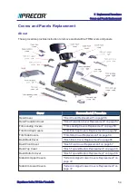
Страница 61: ...p Covers Replacement on page 62 Trim Side Covers Trim Side Cover Replacement on page 64 Dash Back Cover Dash Back Cover Replacement on page 66 Dash Front Cover Dash Front Cover Replacement on page 67 Dash Top Cover Dash Top and Bottom Replacement on page 68 Dash Bottom Cover Dash Top and Bottom Replacement on page 68 Side Arm Upper Covers Side Arm Upper Lower Covers Replacement on page 72 Side Arm...

Страница 62: ...Experience Series 700 Line Treadmills 55 5 Replacement Procedures Covers and Panels Replacement ...

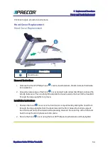
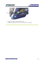
Страница 63: ... towards the back of the treadmill through the targa uprights to remove Installation Instructions 1 Position the hood cover over the front motor compartment by sliding the hood front through the targa uprights from the back towards the front Grasp the bottom edge of the hood cover and pull outwards while pressing down on the cover top at the front and back to snap the tab clip fasteners into place...

Страница 64: ...ips hood transition cover fasteners Pull down and away from the frame rail to release tab clips and remove the cover 3 Repeat procedure for both left and right covers Installation Instructions Repeat procedure for both the left and right covers 1 Position the hood transition cover top flange under the targa upright and press to lock tab clips in place Secure using the two 3 Phillips fasteners and ...

Страница 65: ...epeat procedure for both left and right covers 3 Replace the hood cover see Hood Cover Replacement on page 56 Experience Series 700 Line Treadmills 58 5 Replacement Procedures Covers and Panels Replacement ...

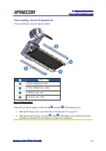
Страница 66: ...uctions The same procedure applies to both the left and right trim landing covers 1 Remove the hood cover see Hood Cover Replacement on page 56 2 Remove the trim landing cover left right 3 Phillips screw washer and bush ing fastener hardware Retain fastener hardware for installation Experience Series 700 Line Treadmills 59 5 Replacement Procedures Covers and Panels Replacement ...

Страница 67: ...the keeper block 2 Grab the outer edge and the inside edge at the rear of the trim landing cover see figure lift point and lift up to release the rear tab clip Continue to slide the cover rearward to remove It requires a strong pull to unsnap and release the cover rear tab clip 3 Repeat the same process to remove both the left and right trim landing covers Installation Instructions Experience Seri...

Страница 68: ...rear cover tab clip in place 3 Secure the rear tab clip by fully tightening the 2 Phillips keeper block fastener 4 Secure the front of the trim landing cover using the 3 Phillips screw washer and bush ing fastener hardware Fully tighten the fastener 5 Repeat installation procedure for both the left and right trim landing covers 6 Reinstall the hood cover see Hood Cover Replacement on page 56 Exper...

Страница 69: ...emove the left and right trim landing covers see Covers and Panels Replacement on page 54 3 Remove the three 3 Phillips trim end cap cover left right fastener screws One fastener on the top one fastener on the end and one fastener on the bottom Retain fastener hardware for installation TIP Use a short stub 3 Phillips screwdriver to remove the bottom end cap fastener Experience Series 700 Line Trea...

Страница 70: ...ecure using the three 3 Phillips screw fasteners One fastener on the top one fastener on the end and one fastener on the bottom 2 Repeat procedure for both the left and right end cap covers 3 Reinstall the left and right trim landing covers see Covers and Panels Replacement on page 54 4 Reinstall the hood cover see Hood Cover Replacement on page 56 5 Repeat the same installation procedure to insta...

Страница 71: ...ing cover see Covers and Panels Replacement on page 54 3 Remove the hood transition cover see Covers and Panels Replacement on page 54 4 Starting from the front moving reward use a standard flat blade screwdriver to release unsnap the top of the trim side cover left right from the five anchor mount clips Hold the cover while releasing the upper anchor bracket clips and then pull down Experience Se...

Страница 72: ... attached at all five anchor mounts 2 Next use the palm of your hand to strike the top of the cover at each of the five anchor mounts to engage and lock the cover in place Make sure that the trim side cover is securely attached at each of the five anchor mounts 3 Reinstall the hood transition cover see Covers and Panels Replacement on page 54 4 Reinstall the trim landing cover see Covers and Panel...

Страница 73: ...e remaining four top screws Carefully hold the cover from falling while removing the fasteners Retain fastener hardware for installation Installation Instructions 1 Reinstall and hold the back cover into position Then nstall the top four 3 phillips screws first followed by the remaining three bottom screws Fully tighten all fasteners Experience Series 700 Line Treadmills 66 5 Replacement Procedure...

Страница 74: ...front cover Retain fastener hardware for installation Installation Instructions 1 Reinstall front cover and secure using the four 3 Phillips screw fasteners 2 Reinstall the console refer to the treadmill assembly guide 700 Line Treadmill Assembly Guide P N 304387 101 3 Reinstall the back cover and secure using the seven 3 screw fasteners see Covers and Panels Replacement on page 54 4 Operate the t...

Страница 75: ...assy bottom cover Retain fastener hardware for installation 2 Carefully flip the dash top cover over and remove the four 2 Philips emergency stop switch E Stop fasteners Carefully lay the E Stop switch on the HHHR 1 assy bracket and remove the dash top cover Retain fastener hardware for installation 1Hand Held Heard Rate Experience Series 700 Line Treadmills 68 5 Replacement Procedures Covers and ...

Страница 76: ...3 Remove the dash bottom cover from between the dash assembly weldment cross member and HHHR bar Experience Series 700 Line Treadmills 69 5 Replacement Procedures Covers and Panels Replacement ...

Страница 77: ...r and HHHR bar 2 Reinstall the E Stop switch onto the dash top cover and secure using the four 2 Philips fasteners Make sure the interface cable electrical red black white black con nections are correctly attached and secure Experience Series 700 Line Treadmills 70 5 Replacement Procedures Covers and Panels Replacement ...

Страница 78: ...ke sure the interface cable is routed correctly and not pinched Make sure that the stop safety clip lanyard is correctly positioned in the cover cut out is not pinched and freely moves when pulled and retracted Experience Series 700 Line Treadmills 71 5 Replacement Procedures Covers and Panels Replacement ...

Страница 79: ...e for installation 2 Remove the one 3 Phillips screw from the upper side arm cover Pull the cover up and forward to remove Retain fastener hardware for installation Installation Instructions Repeat procedure for both the left and right upper and lower side arm covers 1 Position the upper side arm cover onto the side arm weldment and press to lock the tab clips in place Secure using the one 3 Phill...

Страница 80: ... 1 Switch the power OFF and unplug1 the power cord TIP For easier access raise the incline to maximum before removing input power Access the service Hardware Validation 51765761 and use the CROSSRAMP INCLINE Test to raise the incline and then remove power 1Disconnect a device power cord plug or cable connector from the power receptacle or outlet Experience Series 700 Line Treadmills 73 5 Replaceme...

Страница 81: ...ain fastener hardware for installation Installation Instructions 1 Connect the replacement power cord into the power cord AC input assembly 2 Position power cord cable clamp over the power cord plug and fully tighten the clamp fasteners 3 Reinstall the hood cover see Hood Cover Replacement on page 56 4 Connect the power cord and switch the ON OFF circuit breaker ON 5 Do the Operation Verification ...

Страница 82: ...ns the Power Cord Inlet Assembly the ON OFF SW Circuit Breaker and the ASL1 PCA board The Power Entry Assembly Bracket must be removed to access these components ID Description Power Entry Assembly Bracket Power Cord Inlet Assy ON OFF SW Circuit Breaker ASL PCA Board 1Active Status Light Service and maintenance status light Experience Series 700 Line Treadmills 75 5 Replacement Procedures ON OFF S...

Страница 83: ...Wire Diagram Power Entry Assembly wire diagram Procedure Review entire procedure before starting Experience Series 700 Line Treadmills 76 5 Replacement Procedures ON OFF SW Circuit Breaker Replacement ...

Страница 84: ...incline to maximum before removing power Access the service Hardware Validation 51765761 and use the CROSSRAMP INCLINE Test to raise the incline and then remove power 2 Remove the hood cover see Hood Cover Replacement on page 56 1Disconnect a device power cord plug or cable connector from the power receptacle or outlet Experience Series 700 Line Treadmills 77 5 Replacement Procedures ON OFF SW Cir...

Страница 85: ... ON OFF SW Circuit Breaker and secure using the two 2 Phillips fasteners 2 Reconnect the two brown input power wires or two brown and two blue for the 240 Vac option on the ON OFF SW Circuit Breaker see on page 75 3 Reinstall the Power Entry Assembly bracket and secure using the four 3 Phillips fasteners Make sure that the wire cables are not pinched or damaged during install ation 4 Reinstall the...

Страница 86: ...mbly the ON OFF SW Circuit Breaker and the ASL PCA board The Power Entry Assembly Bracket must be removed to access these components ID Description Power Entry Assembly Bracket Power Cord Inlet Assy ON OFF SW Circuit Breaker ASL PCA Board Wire Diagram Power Entry Assembly wire diagram 1Active Status Light Service and maintenance status light Experience Series 700 Line Treadmills 79 5 Replacement P...

Страница 87: ...Procedure Review entire procedure before starting Experience Series 700 Line Treadmills 80 5 Replacement Procedures ASL PCA Replacement ...

Страница 88: ...four 3 Phillips fasteners and remove the Power Entry Assembly bracket Hold the bracket while removing to prevent wire cable damage Retain fastener hardware for installation 4 Disconnect the ASL interface cable RJ11 connector see Wire Diagram on page 79 5 Remove the ASL PCA Bracket by pressing the inner and outer tab clips on the bot tom underside of the Power Entry Assembly Bracket while lifting t...

Страница 89: ...t pinched or damaged during install ation 5 Reinstall the hood cover see Hood Cover Replacement on page 56 6 Connect the power cord and switch the ON OFF circuit breaker ON 7 Verify the ASL light operation a Verify that the ASL light is Solid Blue If the ALS light is Pulsing Blue Pulsing Yel low or Solid Yellow resolve the issue and reset the ASL to Solid Blue 8 Do the Operation Verification tests...

Страница 90: ...es are included in the Dash Top and Bottom Cover Removal Installation procedure see Dash Top and Bottom Replacement on page 68 2 Do the Operation Verification tests see Operation Verification on page 15 and return to service Experience Series 700 Line Treadmills 83 5 Replacement Procedures E Stop Emergency Switch Replacement ...

Страница 91: ...ontroller MC is located in the Drive Motor compartment at the front of the tread mill under the hood cover ID Description Motor Controller MC Lift Motor Drive Motor Line Filter Power Entry Assy Module 1Motor Controller Module Experience Series 700 Line Treadmills 84 5 Replacement Procedures Motor Controller MC Replacement ...

Страница 92: ...MC Wire Diagram Experience Series 700 Line Treadmills 85 5 Replacement Procedures Motor Controller MC Replacement ...

Страница 93: ...ition MC I O connectors The MC interface input output connectors are located on the front and back sides of the MC housing Experience Series 700 Line Treadmills 86 5 Replacement Procedures Motor Controller MC Replacement ...

Страница 94: ...Experience Series 700 Line Treadmills 87 5 Replacement Procedures Motor Controller MC Replacement ...

Страница 95: ... 2 8 VDC 3 TCD DATA OUTPUT 4 DIGITAL GROUND 5 8 VDC 6 RXD DATA INPUT 7 DIGITAL GROUND 8 E STOP DBR11 DYNAMIC BRAKE RESISTOR SENSE 1 THERMAL RESISTOR SENSE 2 THERMAL RESISTOR SENSE MON MONITOR ASL2 PCA INTERFACE CABLE 1 8 VDC 2 BOOT_EN 3 TX 4 8V GND 5 D_RESET 1Dynamic Brake Resistor The dynamic brake resistor dissipates power generated from the main motor 2Active Status Light Service and maintenanc...

Страница 96: ...NC 4 WHITE MOTOR COMMON 5 WHITE POTENTIOMETER WIPER 6 NC 7 RED MOTOR EXTEND 8 BLK MOTOR RETRACT GFX1 not used not used Notes 1 TRM800 14 treadmills only 1Ground Effects Impact Control Systtem Patented treadmill design that out performs a nat ural running surface absorbs high impact movement reduces joint stress and minimizes fatique and supports a solid adn controlled push off Experience Series 70...

Страница 97: ...erface cable connector is located under the MC top cover Component PIN Description Fan motor 1 Black 24V GND 2 Yellow Fault_signal 3 Red 24 VDC Experience Series 700 Line Treadmills 90 5 Replacement Procedures Motor Controller MC Replacement ...

Страница 98: ...he left side of the MC housing ASL State DESCRIPTION Green Normal operation Yellow Indicates a fault condition refer to the error log for more information Experience Series 700 Line Treadmills 91 5 Replacement Procedures Motor Controller MC Replacement ...

Страница 99: ...o disconnect the attached I O2 interface cable connectors see Motor Controller MC Replacement on page 84 Note The COMM connector contacts have an application of dielectric grease to ensure proper electrical contact Do not wipe off clean or remove the dielec tric grease Installation Instructions 1 Place the MC into the drive motor compartment and reconnect the removed MC I O cable connectors It wil...

Страница 100: ...s Hold down PAUSE to access the Error Log select OK to view error codes and then hold down QUICK START to clear the Error Log of all error codes b Clearing the Error Log resets the ASL and MC status lights Verify that the ASL status light is blue and the MC status light is green P62 P80 and P82 a Reset the ASL and MC status lights Access the service Settings menu 5 1 7 6 5 7 6 1 select Maintenance...

Страница 101: ... Replacement on page 54 3 Remove the left and right trim landing covers see Trim Landing Covers Replacement on page 59 4 Relax the running belt tension by loosening the left and right 5 16 hex key tension adjustment bolts Alternately loosen the left and right adjustment bolts in 1 4 turn 1Disconnect a device power cord plug or cable connector from the power receptacle or outlet Experience Series 7...

Страница 102: ...or tension hardware mechanism 5 Walk the Drive Belt off the Drive Roller pulley and then the Drive Motor pulley Tem porarily place the Drive Belt on the inside of the Drive Roller pulley TIP Use turn the Drive Motor flywheel to make it easier to turn the motor pul ley and help walk the belt onto or off the Drive Motor and Drive Roller pulleys 6 Remove the left side Dust Guard 3 Phillips screw fste...

Страница 103: ...hardware for installation 8 Lift the Drive Roller enough to remove the Drive Belt off the pulley Lift the left side of the Dust Guard enough to slide the belt from the Dust Guard and remove from the treadmill Experience Series 700 Line Treadmills 96 5 Replacement Procedures Drive Belt Replacement ...

Страница 104: ...Experience Series 700 Line Treadmills 97 5 Replacement Procedures Drive Belt Replacement ...

Страница 105: ...all the Drive Belt over the Dust Guard 2 Lift the Drive Roller enough to place the Drive Belt onto the Drive Roller pulley Reinstall the Drive Roller into the left and right mounting brackets Experience Series 700 Line Treadmills 98 5 Replacement Procedures Drive Belt Replacement ...

Страница 106: ...ification see Running Belt Tension and Tracking Adjustment on page 40 Do not verify tracking or apply power at this step in the process the running belt tracking will be verified after the Drive Belt is installed 3 Install the drive belt Place the Drive Belt onto the drive pulley and then walk the belt onto the Drive Motor pulley Experience Series 700 Line Treadmills 99 5 Replacement Procedures Dr...

Страница 107: ...d Alignment Adjustment on page 36 6 Connect the power cord and switch the power ON 7 Operate the treadmill and verify the running belt tracking see Running Belt Tension and Tracking Adjustment on page 40 8 Reinstall the left and right trim landing covers see Trim Landing Covers Replacement on page 59 9 Reinstall the hood cover see Covers and Panels Replacement on page 54 10 Do the Operation Verifi...

Страница 108: ...cover ID Description Drive Motor Procedure Review entire procedure before starting Removal Instructions 1 Switch the power OFF and unplug1 the power cord 2 Remove the hood cover see Hood Cover Replacement on page 56 1Disconnect a device power cord plug or cable connector from the power receptacle or outlet Experience Series 700 Line Treadmills 101 5 Replacement Procedures Drive Motor Replacement ...

Страница 109: ...socket or nut driver to remove the Drive Motor static bleed resistor ground wire Orange wire Retain fastener hardware for installation 5 Use tape or marker to make a motor base position reference mark This reference mark will be used to help position the replacement motor installation position 6 Remove Drive Belt tension by loosening the four Drive Motor 1 2 hex head fasten ers Remove the Drive Be...

Страница 110: ... and bottom washers fastener hard ware a If you made a motor base install reference mark prior to removal adjust the Drive Motor base position to the motor base install reference mark and fully tighten the four 1 2 hex head fasteners b If you did not make a motor base install reference mark prior to removal position the motor base to the rear tab stops minimum belt tension position and fully tight...

Страница 111: ...cted to the frame When the ground wire is not con nected touching the motor housing could cause static charge electrical shock and personal injury 3 Reconnect the Motor Controller MTH and MOTOR cable connectors see Motor Controller MC Replacement on page 84 Make sure the cable connectors have the correct orientation and alignment before inserting into the MC I O1 connector 1Input and Output Interf...

Страница 112: ...make sure that the cables have freedom of movement and clear of any frame or component edges that could pinch or damage the cable wires 6 Reinstall the drive belt Place the Drive Belt onto the Roller pulley and walk the belt onto the Drive Motor pulley TIP Use turn the Drive Motor flywheel to make it easier to turn the motor pulley and help walk the belt onto or off the Drive Motor and Drive Rolle...

Страница 113: ...10 Do the Operation Verification tests see Operation Verification on page 15 and return to service Experience Series 700 Line Treadmills 106 5 Replacement Procedures Drive Motor Replacement ...

Страница 114: ...nels Replacement on page 54 3 Relax the running belt tension by loosening the left and right 5 16 hex key tension adjustment bolts Alternately loosen the left and right adjustment bolts in 1 4 turn incre ments so that the running belt tension is evenly removed Only use hand tools and not power tools which could cause damage to the take up roller tension mechanism 1Disconnect a device power cord pl...

Страница 115: ...7 16 hex head fasteners and remove the Dust Guard Retain fastener hardware for installation 5 Remove the Drive Belt Walk the belt off the Drive Roller pulley and remove 6 Remove the one 3 Phillips screw fastener per keeper and remove the left and right Roller keepers Retain fastener hardware for installation Experience Series 700 Line Treadmills 108 5 Replacement Procedures Drive Roller Replacemen...

Страница 116: ...ller from the mounting brackets Slide the Drive Roller through the running belt and remove Installation Instructions 1 Place the Drive Roller thru the Running Belt and then set the Roller back into position in the mounting brackets Experience Series 700 Line Treadmills 109 5 Replacement Procedures Drive Roller Replacement ...

Страница 117: ...the Take up and Drive rollers and tension to specification see Running Belt Tension and Tracking Adjustment on page 40 Do not verify tracking or apply power at this step in the process the running belt tracking will be verified after the Drive Belt is installed Experience Series 700 Line Treadmills 110 5 Replacement Procedures Drive Roller Replacement ...

Страница 118: ... 6 Make sure the Drive Belt pulley alignment is correct and then tension the Drive Belt to specification see Drive Belt Tension and Alignment Adjustment on page 36 7 Connect the power cord and switch the ON OFF circuit breaker to ON 8 Operate the treadmill and verify the running belt tracking see Running Belt Tension and Tracking Adjustment on page 40 9 Reinstall the hood cover see Covers and Pane...

Страница 119: ... by loosening the left and right 5 16 hex key Take up roller tension adjustment bolts Alternately loosen the left and right adjustment bolts in 1 4 turn increments so that the running belt tension is evenly removed Only use hand tools and not power tools to adjust tension CAUTION Only use hand tools to adjust tension Power tools can easily over and or under tension causing damage to the belt and o...

Страница 120: ...t drag across the deck surface while removing causing damage to the deck surface Installation Instructions 1 Insert the Take up roller through the running belt so that the roller shaft end with the hole and slot inserts is on the left side and the end with the flat sided roller shaft is on the right CAUTION Make sure the Take up roller does not drag across the deck surface while inserting through ...

Страница 121: ...he Drive and Take up rollers Tension to specification and verify tracking see Running Belt Tension and Tracking Adjustment on page 40 5 Reinstall the left and right Landing Trim covers see Covers and Panels Replacement on page 54 and hood cover see Covers and Panels Replacement on page 54 Experience Series 700 Line Treadmills 114 5 Replacement Procedures Take up Roller Replacement ...

Страница 122: ...6 Do the Operation Verification tests see Operation Verification on page 15 and return to service Experience Series 700 Line Treadmills 115 5 Replacement Procedures Take up Roller Replacement ...

Страница 123: ...ns 1 Switch the power OFF and unplug1 the power cord 2 Remove the hood cover see Covers and Panels Replacement on page 54 and left right Trim Landing covers see Covers and Panels Replacement on page 54 1Disconnect a device power cord plug or cable connector from the power receptacle or outlet Experience Series 700 Line Treadmills 116 5 Replacement Procedures Belt and Deck Replacement Procedure ...

Страница 124: ...for installation TIP Avoid applying downward pressure on the bolts while removing Pressing down on the bolts can push the nuts out of the pivot housing Reinsert the nut into the pivot housing if this occurs 6 Remove the two 5 32 hex key bolt front deck fasteners These fasteners are attached to the left and right front GFX1 Cushion tinnerman clips Retain fastener hardware for installation 1Ground E...

Страница 125: ... sides of the removed deck are used discard the deck and replace with a new deck CAUTION A new deck surface must used with each new running belt replacement Installation Instructions 1 Reinstall the deck into the running belt Make sure the running belt direction is correct There are two direction indicators the belt logo and the Run direction arrow printed on the inside of the belt right edge Make...

Страница 126: ...fication 27 33 in lbs 3 1 3 7 Nm Its important to correctly torque these fasteners or they may loosen with use Retain fastener hardware for installation IMPORTANT Its important to correctly torque the front deck fasteners at each deck replacement and every PM1 service interval or the screws may prematurely loosen 1Preventative Maintenance Daily Weekly Monthly and Quarterly scheduled maintenance Ex...

Страница 127: ...assemblies The 1 2 fastener nuts are press fit into the bottom of the deck pivot housing Be aware that the nuts can fall from the housing as the bolts are being installed and fall to the floor You may need to hold the huts in place while tightening these fasteners Experience Series 700 Line Treadmills 120 5 Replacement Procedures Belt and Deck Replacement Procedure ...

Страница 128: ... see Running Belt Tension and Tracking Adjustment on page 40 8 Reinstall the hood cover see Covers and Panels Replacement on page 54 and left right Landing Trim covers see Covers and Panels Replacement on page 54 9 Connect the power cord and switch the ON OFF circuit breaker ON 10 Do the Operation Verification tests see Operation Verification on page 15 and return to service Experience Series 700 ...

Страница 129: ...ocedure before starting 1 Remove the hood cover see Hood Cover Replacement on page 56 2 You can access the lift motor jackscrew in one of two methods 1 by raising the tread mill provideding access from the front of the treadmill or 2 by laying the treadmill on its side This procedure uses the front access method If you do not have supports avail able then use the alternative side access method see...

Страница 130: ... on the supports Verify the supports are stable and secure carrying the weight of the treadmill Continue lowering the incline level to 0 Incline level 0 is the lift motor calibration reference incline level IMPORTANT Its important to set the incline level to 0 calibration ref level before switching the power OFF 6 Switch the power OFF and unplug1 the power cord 7 Disconnect the lift motor interfac...

Страница 131: ... or GRN YEL from the frame chassis ground screw fastener 9 Remove the extension tube hitch pin and clevis pin fastener hardware from the lift plat form mounting bracket Hold the lift platform while removing the clevis pin and carefully rest on the floor 1Input and Output Interface Experience Series 700 Line Treadmills 124 5 Replacement Procedures Lift Motor Replacement ...

Страница 132: ...and clevis pin fastener from the frame pan mounting bracket Hold the lift motor while removing fasteners and carefully remove from the treadmill Installation Instructions Experience Series 700 Line Treadmills 125 5 Replacement Procedures Lift Motor Replacement ...

Страница 133: ... the top of the extension tube nut and the lift motor actuator housing Adjust the calibration distance to specification between 1 1 8 in 1 3 16 in 2 8 cm 3 0 cm IMPORTANT Make sure the extension tube does not rotate after setting the cal ibration distance Use tape to mark the extension tube position on the jackscrew Lift motor installation 6 Clean and apply a thin layer of synthetic grease to the ...

Страница 134: ...y rotate the extension tube to align the clevis pin mounting holes Choose an adjustment direction that will minimize the change to the extension tube calibration distance Firmly hold the jackscrew from turn ing while adjusting rotating the extension tube Experience Series 700 Line Treadmills 127 5 Replacement Procedures Lift Motor Replacement ...

Страница 135: ...T connector Route cable and secure in the frame routing cable clamp Connect the ground wire GRN or GRN YEL to the chassis ground screw and fully tighten Experience Series 700 Line Treadmills 128 5 Replacement Procedures Lift Motor Replacement ...

Страница 136: ...0 position WARNING Keep hands and appendages clear of the incline platform assembly before switching power ON Switching power ON will cause the incline platform to move to the level 0 Home position 11 Access the service menu 51765761 and select the INCLINE TEST Increase the incline level enough to lift the treadmill frame off the supports 12 Remove the supports and clear any other items that might...

Страница 137: ...levels Make sure that there are no active Incline function related error codes 16 Do the Operation Verification tests see Operation Verification on page 15 and return to service Experience Series 700 Line Treadmills 130 5 Replacement Procedures Lift Motor Replacement ...

Страница 138: ... Replacement on page 59 3 Remove the left and right trim side covers see Covers and Panels Replacement on page 54 4 You can access and remove the lift platform from the front of the treadmill or by laying the treadmill on its side This procedure uses the front access method If you do not have supports available then use the alternative side access method see Side lift plat form assembly access on ...

Страница 139: ...e supports Keep the wheels as close to floor as possible without touching the floor making sure all the weight of the treadmill is carried by the supports Verify the supports are stable and secure car rying the weight of the treadmill Remove the lift platform 8 Use tape to mark the location of the extension tube on the jackscrew Then remove the lift motor extension tube hitch pin and clevis pin fa...

Страница 140: ...e extension tube position on the jackscrew Allowing the extension tube to rotate will change the cal ibration distance nullifying the calibration If the extension tube is rotated recalibrate the lift motor before reinstalling 9 Remove right lift platform pivot hitch pin Remove left lift platform pivot hitch pin and Experience Series 700 Line Treadmills 133 5 Replacement Procedures Lift Platform Re...

Страница 141: ...ion Installation Instructions 1 Install the lift platform left and right pivot brackets into position and insert the right and left clevis pins Add the spacer to the left clevis pin and secure using the hitch pin Secure the right clevis pin with the hitch pin Experience Series 700 Line Treadmills 134 5 Replacement Procedures Lift Platform Replacement ...

Страница 142: ... lift platform assembly access on page 49 to upright the treadmill WARNING Keep hands and appendages clear of the incline platform assembly before switching power ON Switching power ON will cause the incline platform to move to the level 0 Home position 2 Access the service menu 51765761 and select the INCLINE TEST Increase the incline level enough to lift the treadmill frame off the supports 3 Re...

Страница 143: ...trim landing covers see Trim Landing Covers Replacement on page 59 8 Reinstall the hood cover see Hood Cover Replacement on page 56 9 Do the Operation Verification tests see Operation Verification on page 15 and return to service Experience Series 700 Line Treadmills 136 5 Replacement Procedures Lift Platform Replacement ...

Страница 144: ...ative process best implemented utilizing a systematic approach that efficiently targets the issue cause allowing correct equipment repairs and return to service The following information will help you to systematically troubleshoot and resolve issues Basic Steps Validate the customer reported issue The failure that is reported may differ from your observations as a trained technician Many reported...

Страница 145: ...lve the issue Refer to the Error Code Troubleshooting Guide for error code descriptions and repair infro mation IMPORTANT Error Code description and Troubleshooting information is contained in the Error Code Troubleshooting Guide see Error Code Guide pdf Note Not all failures trigger an error event code Many issues are purely mechanical in nature and therefore cannot trigger an error event code Ve...

Страница 146: ...owse the list of available Troubleshooting procedures for related Troubleshooting inform ation Verify service bulletins Review the list of machine service bulletins and tech tips and verify that there are no current bulletins that may fix the issue Standard Error Codes About There is a set of standard error codes implemented across Precor exercise equipment Error codes are system generated error c...

Страница 147: ...sage will show To remove error codes select the error code and press hold the QUICK START key until the NO ERRORS message shows P62 P80 and P82 Access Hardware Validation 5 1 7 6 5 7 6 1 select About CPA Event Log Note Unlike the Error Log error codes cannot be manually removed from the CPA Event Log Available Error Codes A complete list of error codes including the code description related issues...

Страница 148: ... Event Log and not the Event Log for viewing machine troubleshooting error codes The CPA Event Log filters out non related error codes and only shows error codes related to machine failure issues Always review the Error Log or CPA Event Log when troubleshooting an issue The error logs will contain any triggered error code events and related information You can then refer to Error Code Troubleshoot...

Страница 149: ...ror Log Press and hold the PAUSE RESET key for a minimum of 6 seconds to open the Error Log and view all logged error codes If there are no logged error codes the Stuck Key message will show To remove error codes select the error code and press hold the QUICK START key until the NO ERRORS message shows P62 P80 and P82 Access Hardware Validation 5 1 7 6 5 7 6 1 select About CPA Event Log Note Unlik...

Страница 150: ...ent Log menu Use the touch screen vertical scrollbar to scroll up down thru the list of error codes The P62 P80 and P82 CPA Event Log provides the same error code data found in the P10 P20 and P30 Error Log in addition to the event date time stamp information Tne CPA ERROR identifier in the error code output message indicates that this is a machine fault error code that can be used along with the ...

Страница 151: ...Unlike the Error Log used on P10 P20 and P30 you cannot manually delete clear error codes from the CPA Event Log or Event Log Experience Series 700 Line Treadmills 144 6 Troubleshooting ...

Страница 152: ...or codes down one position When the memory is full the oldest error code is pushed off the stack and removed from memory When an error event is detected the error code information will be stored into the error log or CPA Event Log However when multiple instances of the same error code event occur within the same Hour or Odometer reading only the first occurrence will be logged Either the one hour ...

Страница 153: ... code select the error code to be removed and press hold the QUICK START key for a minimum of 6 secs until the NO ERRORS message shows TIP Error Log Delete Short Cut Press and hold the PAUSE RESET key for a minimum of 6 seconds to open the Error Log and view all logged error codes If there are no logged error codes the Stuck Key message will show To remove error codes select the error code and pre...

Страница 154: ...0 P20 and P30 you cannot manually delete clear error codes from the CPA Event Log or Event Log Active Status Light ASL About The Active Status Light ASL1 is a service and maintenance status light located on the front lower center of the TRM front hood cover The ASL provides a visual indication of the machine operational status The current implementation supports four states 1 solid blue indicates ...

Страница 155: ...s shown before a lower priority state until cleared l The console UPCA1 determines the ASL state using inputs from the error log and main tenance counter During active operation workout in progress or during the pause state the console transmits the ASL state to the lower control board LPCA2 l Only direct error code and maintenance counter data is used to determine the current machine ASL state No...

Страница 156: ...unts down the active use hours to 0 When the counter reaches zero hours the ASL will begin pulsing blue indicating preventative maintenance is due Yellow Solid Indicates an error has occurred was self corrected and the machine can be used The fault can be cleared Yellow Pulsing There is a current non recoverable fault condition there is a loss of a major func tion and the machine id out of service...

Страница 157: ... the service access menu see View ing the current ASL state below l Error code events will still affect the ASL state condition even when the Maintenance Reminder is set to OFF On P10 P20 and P30 consoles Access Club Settings 5 6 5 1 5 6 5 MAINT CONFIG select ON or OFF On P62 P80 and P82 consoles Access Club Settings 5 6 5 1 5 6 5 Maintenance menu Maintenance Reminder select ON or OFF Viewing the ...

Страница 158: ... error condition causing the ASL pulsing yellow must first be resolved On P10 P20 and P30 consoles self cleared error codes will change the ASL state to solid yellow Then the error code must be cleared from the Error Log to reset the ASL state to normal solid blue On P62 P80 and P82 consoles self cleared error codes will auto change the ASL state to normal solid blue The ASL yellow and pulsing yel...

Страница 159: ...ou determine that the equipment needs service disconnect all power connections television Ethernet and power and move the equipment away from the exercise area Place an OUT OF SERVICE sign on the equipment and make it clear to all patrons and other users that they must not use it Daily Maintenance Perform the following maintenance tasks daily Daily Task Description Clean the equipment exposed fram...

Страница 160: ...ce of the running belt with a soft dry or damp cloth using an approved cleaner Clean the running belt and deck Clean the running belt and deck see Running Belt and Deck Cleaning Procedure inspect the running belt operation and condition Inspect the running belt for the following possible issues l Belt slipping l Frayed or worn condition l Belt alignment and tracking is centered on the deck and rol...

Страница 161: ...o maximum level Monthly Maintenance Perform the Daily and Weekly task in addition to the following monthly maintenance tasks WARNING DANGER USE EXTREME CAUTION when the rear cover of any TRM is removed Serious injury could result if fingers are pinched between the fly wheel spokes cranks movable arms and the drive weldment Securing the mov able arm to the crank with a clamp is recommended Be aware...

Страница 162: ...g Belt Adjustment procedure Verify the Drive Motor belt tension Verify the Drive Motor belt tension and adjust as neces sary see Drive Motor Belt Tension Adjustment pro cedure Vacuum the front compartment and Motor Controller fan Remove hood and vacuum the compartment and Motor Controller fan It is recommended that you use a static resistant vacuum cleaner Be careful to not put nozzle near PCA ele...

Страница 163: ...ng belt does not stop turn off the power using the ON OFF switch at the front of the treadmill and unplug1 the power cord The treadmill must remain out of service until the stop switch is repaired 2 Get a clean dry cotton towel that is at least 36 inches 1 meter in length and fold it in half lengthwise a Lift the running belt and push the towel through to the other side so that both ends of the to...

Страница 164: ...readmill will begin to run at 1 mph Allow the treadmill to run for one minute while keeping the towel firmly in place WARNING Do not adjust the treadmill s speed or run it higher than 1 mph 5 After one minute stop the treadmill by pressing the STOP button 6 When the belt has fully stopped moving remove the STOP key tether exit the treadmill and turn the power switch to OFF Experience Series 700 Li...

Страница 165: ...e belt several times to clean the top of the deck 8 Remove the towel from beneath the belt 9 Turn the power switch to ON 10 Verify operation and return to service Experience Series 700 Line Treadmills 158 7 Preventative Maintenance Running Belt and Deck Cleaning Procedure ...

Страница 166: ...ich is used to maintain the Error Log ser vice menu The console also controls and sends the ASL7 status state based on the received error codes to the base The LPCA makes use of two main processors the Master also referred to interchangeably as Major and Slave also as Minor 1Dynamic Brake Resistor The dynamic brake resistor dissipates power generated from the main motor 2Active Status Light Servic...

Страница 167: ...munication Interface Cable Active Status Light ASL Active Status Light similar to Treadmill ASL except that operation has been changed for self powered machines A separate microprocessor and software on the LPCA control the color and flashing of the LED A button near the light is used to wake up the entire system tem porarily to check its color and to clear the status color if pressed long enough ...

Страница 168: ...System Wiring Diagram System Overview Wire Diagram System Overview Wire Diagram Experience Series 700 Line Treadmills 161 8 Theory of Operation ...

Страница 169: ...Power Entry Assemble Wire Diagram Power Entry Assembly Wire Diagram Experience Series 700 Line Treadmills 162 8 Theory of Operation System Wiring Diagram ...

Страница 170: ...COMM Cable Wire Diagram COMM Cable Wire Diagram Experience Series 700 Line Treadmills 163 8 Theory of Operation System Wiring Diagram ...

Страница 171: ...Console Wire Diagram Console Wire Diagram Experience Series 700 Line Treadmills 164 8 Theory of Operation System Wiring Diagram ...

Страница 172: ...Experience Series 700 Line Treadmills 165 8 Theory of Operation System Wiring Diagram ...

Страница 173: ...t current Exploded View Diagram and Parts Identification List information l Precor Connect Partner website IMPORTANT Always purchase OEM replacement parts and hardware from Precor If you use parts not approved by Precor you could void the Precor Limited Warranty Use of parts not approved by Precor may cause injury Exploded View Diagram Continue to view the hard copy version Experience Series 700 L...

Страница 174: ...Experience Series 700 Line Treadmills 167 8 Theory of Operation Exploded View Diagram ...

Страница 175: ...Experience Series 700 Line Treadmills 168 8 Theory of Operation Exploded View Diagram ...

Страница 176: ...Experience Series 700 Line Treadmills 169 8 Theory of Operation Exploded View Diagram ...

Страница 177: ...Experience Series 700 Line Treadmills 170 8 Theory of Operation Exploded View Diagram ...

Страница 178: ...Experience Series 700 Line Treadmills 171 8 Theory of Operation Exploded View Diagram ...

Страница 179: ...Experience Series 700 Line Treadmills 172 8 Theory of Operation Exploded View Diagram ...

Страница 180: ...Parts List Continue to view the hard copy version Experience Series 700 Line Treadmills 173 8 Theory of Operation Parts List ...

Страница 181: ...Experience Series 700 Line Treadmills 174 8 Theory of Operation Parts List ...

Страница 182: ...Experience Series 700 Line Treadmills 175 8 Theory of Operation Parts List ...

Страница 183: ...Experience Series 700 Line Treadmills 176 8 Theory of Operation Parts List ...

Страница 184: ...rporated No part of this manual may be reproduced in any form or by any means including electronic storage and retrieval or translation into a foreign language without prior agreement and writ ten consent from Precor Incorporated as governed by United States and international copy right laws Precor Incorporated 20031 142nd Ave NE P O Box 7202 Woodinville WA 98072 4002 Ph 1 800 347 4404 Experience ...

Страница 185: ...ry rights Warranty The material contained in this document is provided as is and is subject to being changed without notice in future editions Further to the maximum extent permitted by applicable law Precor disclaims all warranties either expressed or implied with regard to this manual and any information contained herein including but not limited to the implied warranties of mer chantability and...

Страница 186: ...notice until the indicated conditions are fully understood Caution A CAUTION notice denotes a hazard It calls attention to an operating procedure practice or the like that if not correctly performed or adhered to could result in dam age to the product or loss of important data Do not proceed beyond a CAUTION notice until the indicated conditions are fully understood Experience Series 700 Line Trea...

Отзывы: