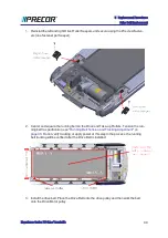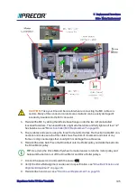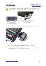
the mounting fasteners. Make sure the I/O cable connectors have the correct orientation
and alignment before inserting into the receiving MC I/O port.
CAUTION
: Take your time and be careful when reconnecting the I/O cable
connector plugs. Many of the connector contacts are small and can be easily
damaged if incorrectly inserted into the receiving connector plug-in.
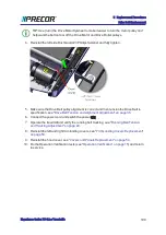
2. Reinstall the MC by sliding the left side base flanges under the two left preinstalled
loosened fasteners. Then install the two right side fasteners and fully tighten all four
fasteners.
3. Route cables and secure using the frame cable clamps. Recheck all cable MC con-
nections and make sure that the cables have freedom of movement and clear of any
frame or component edges that could pinch or damage the cable wires.
4.
Plug
1
in the power cord and switch the power ON.
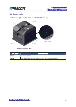
5. Verify the MC status light is green. If the status light is yellow, reset the status light as fol-
lows:
P10, P20, and P30
a. Clear the Error Log of any stored error codes: Hold down PAUSE to access the
Error Log > select OK to view error codes, and then hold down QUICK START
to clear the Error Log of all error codes.
b. Clearing the Error Log resets the ASL and MC status lights. Verify that the ASL
status light is blue and the MC status light is green.
P62, P80, and P82
a. Reset the ASL and MC status lights: Access the service Settings menu
(5,1,7,6,5,7,6,1), select Maintenance > Operating Condition > and the Reset
softkey to reset the ASL and MC status lights. Verify the following Maintenance
menu parameters:
l
Recommended Action: None
l
Operating Condition: Normal
l
Active Status Light: Solid Blue
b. Visually verify that the MC status light is now “green” and the ASL light is “solid
blue”.
c. Repeat selecting the Back softkey to exit and return to the “Welcome” banner
home page.
6. Reinstall the hood cover, see
"Hood Cover Replacement" on page 56
.
7. Do the Operation Verification tests (see
"Operation Verification" on page 15
) and return
to service.
1
Device power cord connector or electrical cable male connector that is inserted into an elec-
trical receptacle "outlet" (also called the plug-in).
Experience Series 700 Line Treadmills
93
5 Replacement Procedures
Motor Controller (MC) Replacement
Содержание Experience TRM700-16
Страница 1: ...Service Manual Experience Series 700 line TRM700 16 Base Treadmill 120 VAC and 240 VAC ...
Страница 19: ...Experience Series 700 Line Treadmills 12 1 Introduction General Information ...
Страница 62: ...Experience Series 700 Line Treadmills 55 5 Replacement Procedures Covers and Panels Replacement ...
Страница 94: ...Experience Series 700 Line Treadmills 87 5 Replacement Procedures Motor Controller MC Replacement ...
Страница 104: ...Experience Series 700 Line Treadmills 97 5 Replacement Procedures Drive Belt Replacement ...
Страница 172: ...Experience Series 700 Line Treadmills 165 8 Theory of Operation System Wiring Diagram ...
Страница 174: ...Experience Series 700 Line Treadmills 167 8 Theory of Operation Exploded View Diagram ...
Страница 175: ...Experience Series 700 Line Treadmills 168 8 Theory of Operation Exploded View Diagram ...
Страница 176: ...Experience Series 700 Line Treadmills 169 8 Theory of Operation Exploded View Diagram ...
Страница 177: ...Experience Series 700 Line Treadmills 170 8 Theory of Operation Exploded View Diagram ...
Страница 178: ...Experience Series 700 Line Treadmills 171 8 Theory of Operation Exploded View Diagram ...
Страница 179: ...Experience Series 700 Line Treadmills 172 8 Theory of Operation Exploded View Diagram ...
Страница 181: ...Experience Series 700 Line Treadmills 174 8 Theory of Operation Parts List ...
Страница 182: ...Experience Series 700 Line Treadmills 175 8 Theory of Operation Parts List ...
Страница 183: ...Experience Series 700 Line Treadmills 176 8 Theory of Operation Parts List ...

