5
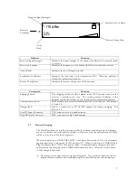
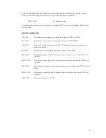
Received Signal Strength
Synthesizer Lock Status
Receiver
Frequency
Battery Charge State
Active
Band
Indicator Function
Received Signal Strength
Indicates the signal strength of the channel the Receiver is currently tuned
to receive.
Receiver Frequency
Indicates the frequency of the channel the Receiver is tuned to receive.
Active Band
Indicates the active frequency band.
Synthesizer Lock Status
Indicates the lock status of the Synthesizer PLL. When the padlock is
closed, the synthesizer is locked.
Battery Charge State
Indicates the current charge state of the batteries.
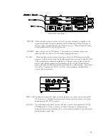
Connection Function
Shipping Switch
The shipping switch should be placed in the OFF position whenever the
receiver is placed in the case. The switch prevents discharge of the
batteries should the ON key on the front panel be inadvertently pressed.
Communications Port
RJ45 modular jack for serial communications to the receiver. See Sections
4.0 and 5.0.
Charger Jack
Jack for connection to 9V AC/DC adapter for battery charging. See
Section 2.2.
Low RF Input Connector
TNC connector for low band antenna
High RF Input Connector
SMA connector for high band antenna
2.2
Battery Charging
The Dual Band Receiver is fully operational while the batteries are being charged. Charging
can occur whether or not the unit is powered on. However, with the unit powered off, there
will be no way to monitor the charge cycle.
When the display shows “BATTERY LOW”, the battery has less than 10% of its maximum
capacity remaining. Connect the AC/DC adapter (9V /300mA) to the unit’s CHARGE jack.
Plug the adapter into a 115V 60 Hz power outlet. An internal battery charger will control
and terminate the charging of the 4 NiMH cells within each unit. Allow about three hours
to fully charge the batteries.
A.)
The charge cycle begins in the charge pending phase. For a period of time, the battery
display area may alternate between displaying the normal battery bar and the message
-110 dBm
Freq:
Band:


