15
Power up the unit with the slide switch on the front of the Battery Box. The software will
respond “RDY” if the communications channel is operating correctly. You can verify the
current settings at any time by typing “HELP?” A summary of commands is displayed.
The current synthesizer frequency is stored in non-volatile memory. When power is applied
to the synthesizer, it will return to the last entered frequency.
Set up the synthesizers, following the recommended sequence:
Set the frequency in MHz
FR=XXXX.yyyy<CR>
Verify the transmitter is enabled
TX?<CR>
Verify the frequency is locked
LD?<CR>
If the LED beside the band select switch is illuminated, the synthesizer is locked and
transmitting.
See Section 9.0 for a complete listing of all commands and error codes.
If desired, connect the RF OUT to power meter or spectrum analyzer to adjust the output
level. Alternatively, the Model 5500 Receiver can be used to adjust the output. See the
procedure described in Section 3.0.
Disconnect serial cable; the transmitter is ready for operation.
8.2
Programming Through the Model 5500 Receiver
The Model 5500 Signal Strength Receiver can be used to setup the Model 5700 Transmitter
frequency when a laptop or PC is not available. This function only works when the
transmitter is set to the same step size as the receiver. When the transmitter is first powered
on, the low band step size is always 10kHz and the high band step size is always 30kHz.
When the receiver is first powered on, the step size is set to the step size that was used when
it was powered down. Whenever the receiver is to be used to program the transmitter
frequency in the field, the user must insure that the receiver low band step size is 10kHz and
the high band step size is 30kHz.
When using RXSCAN software version 2.0 and earlier, the user must insure that that step
size is set to the desired value by manually typing in the desired step size in the command
box located in the upper right hand corner of the window. This is necessary following any
band scan due to an error in the code the resets the low band step size to 10kHz and the
high band step size to 100kHz.
Cable connections and power up:
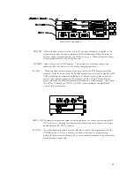
1) Turn on the receiver and the transmitter
2) If programming in the low band, switch the transmitter selector to “CELL”. If
programming in the high band, switch the transmitter to “PCS”. (Substitute “GSM” for
“CELL” and “DCS” for “PCS” if using the GSM/DCS transmitter.)
3) Using the supplied modular cable, install the modular adapter labeled “TX” onto one end.
Plug the other end into the receiver.
4) Plug the “TX” adapter into the appropriate connector, depending on switch position set
in step 2. The low band and high band transmitters are two independent units, so if a low
band frequency is to be programmed, the switch on the transmitter must be in the down


