background image


10 

ERROR RESPONSES


Invalid commands will be acknowledged with an error response.  An error response will consist of 4 
ASCII bytes followed by a carriage return.  The error code consists of the two characters ER followed 

by a two-character error status code. 


ERIC<CR>  

Invalid 

command 


The command was not recognized because it was not in the proper 
format. 


ERIN<CR> 


Invalid number or range 


The data included in the previous command was invalid or out-of-range. 


ERSE<CR>  

Communications 

(UART) 

error 


The last command was not recognized due to a framing error in the serial 

communications.  This error will normally be encountered when the 
host’s serial port does not match the serial port settings specified in this 

document. 


Содержание 5500

Страница 1: ...PRAXSYM Model 5500 Receiver Model 5700 Transmitter User s Manual February 6 2002 ...

Страница 2: ...eiver Commands and Error Codes page 8 6 0 Overview of Model 5700 Transmitter page 11 7 0 Operation of Model 5700 Transmitter page 11 7 1 Control and Indicator Description page 11 7 2 Battery Charging page 13 7 3 Operation with AA Dry Cells page 13 7 4 Operation with External Power Source page 14 8 0 Programming the Synthesizer page 14 8 1 Programming Through a PC page 14 8 2 Programming Through th...

Страница 3: ...0055 002 Cellular band 824 894 MHz PCS band 1930 1990 MHz 310 010055 003 GSM band 925 960 MHz DCS band 1805 1880 MHz The Dual Band Receiver can be used in conjunction with Praxsym s Model 5700 Dual Band Transmitter to take path loss measurements in the low band Cell or GSM and high band PCS or DCS Typically the operator decides which frequency to use for testing by scanning the band with the recei...

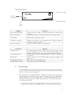
Страница 4: ...n the low and high bands The display will indicate the active band and the last tuned frequency in that band FREQ Press the CTRL and FREQ UP ARROW keys simultaneously to increment the receiver frequency up by one step If these keys are held for more than second the frequency will be changed at 10 times the rate allowing rapid slewing across the band CTRL and FREQ DN ARROW moves the tuned frequency...

Страница 5: ...ial communications to the receiver See Sections 4 0 and 5 0 Charger Jack Jack for connection to 9V AC DC adapter for battery charging See Section 2 2 Low RF Input Connector TNC connector for low band antenna High RF Input Connector SMA connector for high band antenna 2 2 Battery Charging The Dual Band Receiver is fully operational while the batteries are being charged Charging can occur whether or...

Страница 6: ...pulse trickle charge rate When this condition occurs turn the unit off until the batteries have charged to the point that the fast charge phase begins The unit may then be turned back on 2 3 Operation with AA Dry Cells Although the four internal AA Nickel Metal Hydride NiMH batteries should provide sufficient power for most testing situations provision for operation with disposable lead acid or al...

Страница 7: ...t you would like to scan and then initiate the scan Information on controlling the receiver with the RXScan software can be found in appendix A Using the spectrum display or the spreadsheet output of the RXScan software choose a test frequency Tune the receiver to the test frequency Set up the test transmitter to the test frequency using the procedures outlined in Section 8 of this manual The RXSc...

Страница 8: ...ency Set up the receiver following the recommended sequence Set the target band BD X CR 0 low band 1 high band Set the frequency in MHz FR XXXX yyy CR Verify the frequency is locked LD CR See Section 5 0 for a complete listing of all commands and error codes 5 0 Definition of Receiver Commands and Error Codes Put the keyboard in all CAPS mode before entering commands CR represents ENTER SET COMMAN...

Страница 9: ...the current step size setting in the form X XXXX MHz LD CR Returns 1 if the synthesizer is locked 0 if the synthesizer is not locked or output is disabled SS CR Returns the measured signal strength in the form XX y dBm MX CR Returns the highest low band frequency that can be set in the form XXXX yyyy in MHz MX2 CR Returns the highest high band frequency that can be set in the form XXXX yyyy in MHz...

Страница 10: ... ERIC CR Invalid command The command was not recognized because it was not in the proper format ERIN CR Invalid number or range The data included in the previous command was invalid or out of range ERSE CR Communications UART error The last command was not recognized due to a framing error in the serial communications This error will normally be encountered when the host s serial port does not mat...

Страница 11: ...thesizers are as follows Synthesizer Frequency Output Level Step Size Cellular 875 MHz 5 dBm 10 kHz 824 894 MHz Extended Cellular 875 MHz 5 dBm 10 kHz 805 894 MHz GSM 921 MHz 5 dBm 10 kHz 880 960 MHz PCS 1960 2 MHz 5 dBm 30 kHz 1930 1990 MHz Extended PCS 1960 2 MHz 5 dBm 30 kHz 1850 1990 MHz DCS 1785 MHz 5 dBm 30 kHz 1710 1880 MHz Typically the operator decides which frequency to use for testing T...

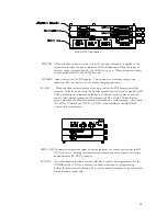
Страница 12: ...green BAND LED will illuminate to indicate which band is selected for the operation and the status of the selected synthesizer The respective PCS or CELL LED will glow green only when the selected synthesizer is locked on a valid frequency Substitute GSM for Cellular and DCS for PCS when refering to the GSM DCS version of the transmitter AMPL ADJ Turning this adjustment screw clockwise increases t...

Страница 13: ...ge using a pulse trickle mode as long as the adapter is plugged into the Battery Box Although the transmitter may be operated during charging if the AC DC adapter is connected after the batteries have discharged below 8 volts the charger will remain in the charge pending phase The batteries will continue to discharge since the unit s operating current is greater than the pulse trickle charge rate ...

Страница 14: ...programmed via a PC or embedded controller Procedures in this section describe setup of synthesizers with a PC or laptop computer as the host interface The synthesizers are programmed using simple ASCII commands from a terminal program See Appendix A to program the transmitters with the RXScan software Select the correct frequency band with the slide switch on the front of the Battery Box Install ...

Страница 15: ...e receiver When the transmitter is first powered on the low band step size is always 10kHz and the high band step size is always 30kHz When the receiver is first powered on the step size is set to the step size that was used when it was powered down Whenever the receiver is to be used to program the transmitter frequency in the field the user must insure that the receiver low band step size is 10k...

Страница 16: ...itter to a low band frequency while in high band range on the receiver this obviously results in an error condition If the user rapidly changes the frequency resulting in rapid invalid frequency assignments to the transmitter the transmitter will lock up and not respond to input If lock up should occur shut off the power to the transmitter flip the switch to the off position and turn it back on 9 ...

Страница 17: ...bled 0 if the output is disabled MX CR Returns the highest frequency that can be set in the form XXXX yyyy in MHz MN CR Returns the lowest frequency that can be set in the form XXXX yyyy in MHz VR CR Return software version X X ERROR RESPONSES Invalid commands will be acknowledged with an error response An error response will consist of 4 ASCII bytes followed by a carriage return The error code co...

Страница 18: ...na ports on the receiver The modular plug of the supplied serial cable should be connected to the receiver while the 9 pin DSUB connector should be connected to a free comm port on the PC 2 2 Connecting to the Receiver Click on File Connect Receiver This action will bring up the connection form If the comm port hooked up to the serial cable is not labeled on the outside of the computer then try Co...

Страница 19: ...ype a valid frequency into the Frequency Scan Range box The leftmost box sets the lower bound of the scan range while the rightmost box selects the upper bound If using the Channel scanning range boxes the Mode box determines whether the channel is interpreted as a Mobile or a Base channel 3 0 Scanning After the range has been selected press the Scan button The raw data communications with the rec...

Страница 20: ...4 0 Using Frequency Bank The Frequency Bank option allows the user to select up to six frequencies to monitor Each time the Scan button is selected readings are taken and can then be logged to an Excel file A user label tag is used to identify the corresponding scan location GPS information see section 2 3 and time stamp can also be implemented ...

Страница 21: ...een When the SCAN button is selected each enabled channel is scanned once and the measured signal strength is displayed A label can be added to each scan to help identify the location or other information important to the scan Once your label has been entered the data can be appended to the active log file by selecting the LOG TO FILE button If the LOG TO FILE button is not selected the data from ...

Страница 22: ...ab a message window should appear reminding the user that the communications cable needs to be disconnected from the receiver and connected to the transmitter The transmitter interface simply sends commands to the transmitter displaying the command and the resulting answer in the Communications window adjacent to the main program window 6 0 Transmitter Frequency Selection To change the transmitter...

Отзывы: