18
HOW TO DEMOUNT SYSTEM 5000
First, remember to demount the connectors with hazardous voltages.
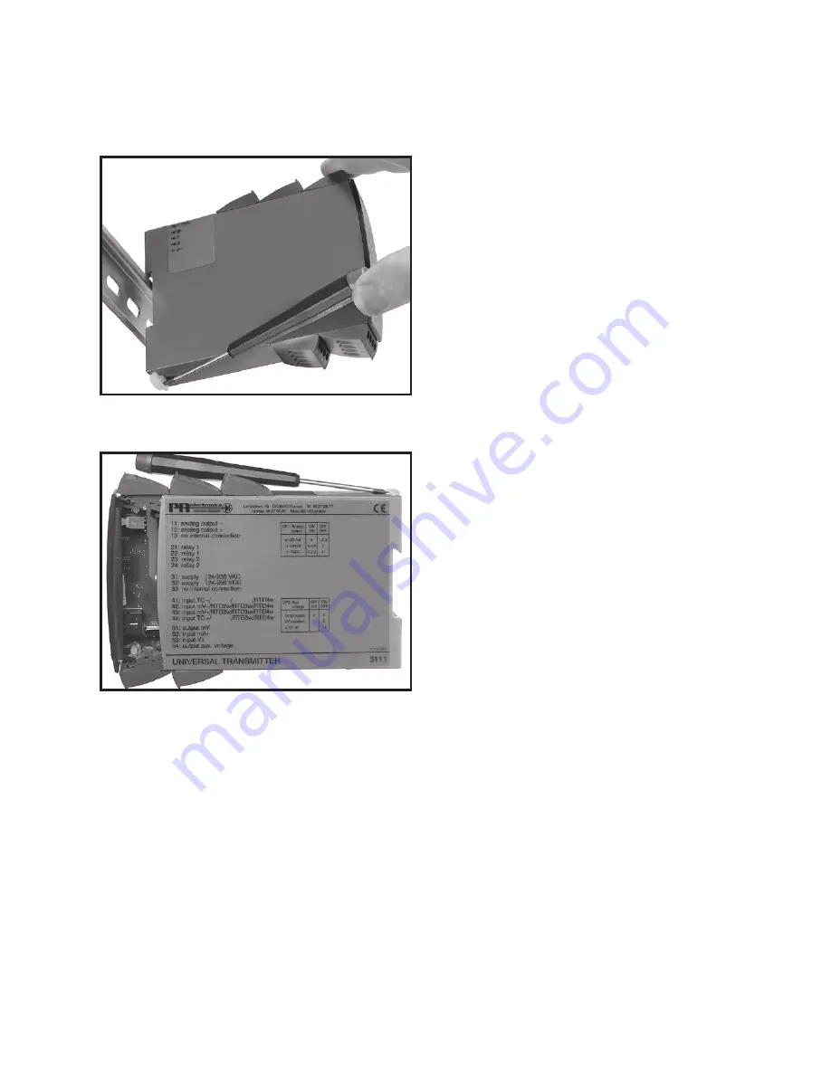
Picture 1:
By lifting the bottom lock, the module
is detached from the DIN rail.
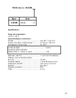
Picture 2:
Then, by lifting the upper lock and
pulling the front plate simultaneously
the PCB is removed.
Switches and jumpers can now be
adjusted.
Содержание 5420B
Страница 10: ...8 2 Trådstransmitter 2 Trådstransmitter Loop alarm Loop alarm Forsy ning Forsy ning ...
Страница 22: ...20 2 wire transmitter 2 wire transmitter Loop alarm Loop alarm Supply Supply ...
Страница 34: ...32 Transmetteur 2 fils Transmetteur 2 fils Alarme de boucle Alarme de boucle Alimen tation Alimen tation ...
Страница 46: ...44 Schleifen alarm Schleifen alarm Versorg ung Versorg ung 2 Draht Umformer 2 Draht Umformer ...


