background image

Programmable displays with a wide se-

lection of inputs and outputs for display of temperature, 
volume and weight, etc. Feature linearisation, scaling, 
and difference measurement functions for programming 
via PReset software.

Interfaces for analogue and digital 

signals as well as HART

®

 signals between sensors / I/P 

converters / frequency signals and control systems in Ex 
zone 0, 1 & 2 and for some modules in zone 20, 21 & 22.

Galvanic isolators for analogue and digital 

signals as well as HART

®

 signals. A wide product range 

with both loop-powered and universal isolators featuring 
linearisation, inversion, and scaling of output signals.

PC or front programmable modules with 

universal options for input, output and supply. This range 
offers a number of advanced features such as process 
calibration, linearisation and auto-diagnosis.

A wide selection of transmitters for DIN 

form B mounting and DIN rail modules with analogue 
and digital bus communication ranging from application- 
specific to universal transmitters.

Displays

Temperature

Isolation

Ex interfaces

Universal

Содержание 5420B

Страница 1: ...DK UK FR DE Side 1 Page 13 Page 25 Seite 37 S I G N A L S T H E B E S T 5 4 2 0 B Ex Power Supply N o 5 4 2 0 B V 1 0 2 I N 1 2 4 5 F r o m s e r n o 0 3 0 1 4 5 0 0 1 ...

Страница 2: ...ctronics A S offre une large gamme de produits pour le traite ment des signaux analogiques et numériques dans tous les domaines industriels La gamme de produits s étend des transmetteurs de température aux afficheurs des isolateurs aux interfaces SI jusqu aux modules universels Vous pouvez compter sur nos produits même dans les conditions d utilisation sévères p ex bruit électrique vibrations et f...

Страница 3: ...egnelse Advarsler 2 Sikkerhedsregler 3 EF overensstemmelserklæring 5 Adskillelse af SYSTEM 5000 6 Anvendelse 7 Teknisk karakteristik 7 Montage installation 7 Applikationer 8 Bestillingsskema 9 Elektriske specifikationer 9 Tilslutninger 11 Blokdiagram 12 ...

Страница 4: ... denne manual så forringes modulets beskyttelsesforanstaltninger ADVARSEL Der må ikke tilsluttes farlig spænding til modulet før dette er fastmonteret og følgende operationer bør kun udføres på modu let i spændingsløs tilstand og under ESD sikre forhold Adskillelse af modulet for indstilling af omskiftere og jumpere Installation ledningsmontage og demontage Fejlfinding på modulet Reparation af mod...

Страница 5: ...de teknisk og sikkerheds mæssigt forsvarligt Operatører er personer som under normal drift med produktet skal indstille og betjene produktets trykknapper eller potentiometre og som er gjort bekendt med indholdet af denne manual Modtagelse og udpakning Udpak modulet uden at beskadige dette og sørg for at manualen altid følger modulet og er tilgængelig Indpakningen bør følge modulet indtil dette er ...

Страница 6: ... og tæt ved modulet Afbryderen skal mærkes således at der ikke er tvivl om at den afbryder spændingen til modulet Produktionsår fremgår af de to første cifre i serienummeret Kalibrering og justering Under kalibrering og justering skal måling og tilslutning af eksterne spændinger udføres i henhold til denne manual og teknikeren skal benytte sikkerhedsmæs sigt korrekte værktøjer og instrumenter Betj...

Страница 7: ...vises til modulets elektriske specifikationer Lavspændingsdirektivet 2006 95 EF og senere tilføjelser EN 61010 1 ATEX direktivet 94 9 EF og senere tilføjelser EN 50014 1997 E inkl A1 A2 EN 50020 2002 E og EN 50281 1 1 1998 inkl A1 ATEX certifikat DEMKO 99ATEX126256 Der kræves ingen ændringer i produktet for at opnå overensstemmelse med de nye standarder EN 60079 0 2009 og EN 60079 11 2012 Bemyndig...

Страница 8: ...ntere tilslutningsklemmerne med farlig spænding Billede 1 Modulet frigøres fra DIN skinnen ved at løfte i den nederste lås Billede 2 Printet udtages ved at løfte i den øverste lås og samtidig trække ud i frontpladen Nu kan switche og jumpere ændres ...

Страница 9: ...ionsfarligt område Spændingsforsyning med failsafe detektering af aktiv strømsløjfe fra 2 tråd stransmittere placeret i eksplosionsfarligt område Teknisk karakteristik PR5420B har relæ med skiftekontakter til rådighed på den sikre side Når loopstrømmen er indenfor den fastsatte grænse er relæet trukket Forsyning og udgange er indbyrdes galvanisk adskilte og ikke stelbundne Montage installation Mon...

Страница 10: ...8 2 Trådstransmitter 2 Trådstransmitter Loop alarm Loop alarm Forsy ning Forsy ning ...

Страница 11: ...ingstemperatur 20 28 C Ledningskvadrat max 1 x 2 5 mm2 flerkoret ledning Klemskruetilspændingsmoment 0 5 Nm Relativ luftfugtighed 95 RH ikke kond Mål HxBxD 109 x 23 5 x 130 mm DIN skinne type DIN 46277 Kapslingsklasse IP20 Vægt 215 g 5420B Dobbelt 2 Type Kanal Bestillingsskema 5420B EMC Immunitetspåvirkning 0 5 Udvidet EMC immunitet NAMUR NE 21 A kriterium gniststøj 1 ...

Страница 12: ... max 2 ARMS Max AC effekt 100 VA Max belastning ved 24 VDC 1 A EEx I S godkendelse DEMKO 99ATEX126256 II 1 GD EEx ia IIC Anvendes for zone 0 1 2 20 21 eller 22 Ex I S data Um 250 V Uo 28 VDC Io 93 mADC Po 0 65 W Lo 3 mH Co 0 08 µF GOST R godkendelse VNIIM VNIIFTRI Cert no Se www prelectronics dk Overholdte myndighedskrav Standard EMC 2004 108 EF EN 61326 1 LVD 2006 95 EF EN 61010 1 PELV SELV IEC 3...

Страница 13: ...11 31 32 33 53 51 52 23 21 22 11 12 13 43 41 42 Tilslutninger Forsyning Udgange til Ex område Kanal 1 Kanal 2 Kanal 2 Sikkert område Kanal 1 DC spænding DC spænding Loop alarm Loop alarm V Gnd V Gnd ...

Страница 14: ...20B CH 1 CH 2 33 53 51 31 23 22 21 43 41 V reg 13 12 11 20 Ω Forsyning yning Kanal 1 Kanal 2 24 230 VAC 24 250 VDC Ex Barriere BLOKDIAGRAM Udgang Udgang Grænse 3 8 og 20 5 mA Komp Rel Relæ fælles Relæ N O Relæ N C ...

Страница 15: ... Warnings 14 Safety instructions 15 EC Declaration of Conformity 17 How to demount SYSTEM 5000 18 Application 19 Technical characteristics 19 Mounting installation 19 Applications 20 Order 21 Electrical specifications 21 Connections 23 Block diagram 24 ...

Страница 16: ... the protection provided by the equipment may be impaired WARNING Until the module is fixed do not connect hazardous voltages to the module The following operations should only be carried out on a disconnected module and under ESD safe conditions Dismantlement of the module for setting of DIP switches and jumpers General mounting wire connection and disconnection Troubleshooting the module Repair ...

Страница 17: ... shoot technically correct and in accordance with safety regulations Operators being familiar with the contents of this manual adjust and operate the knobs or potentiometers during normal operation Receipt and unpacking Unpack the module without damaging it and make sure that the manual always follows the module and is always available The packing should always follow the module until this has bee...

Страница 18: ...and close to the module The power switch should be marked with a label telling it will switch off the voltage to the module Production year can be taken from the first 2 digits of the serial number Calibration and Adjustment During calibration and adjustment the measuring and connection of external voltages must be carried out according to the specifications of this manual The technician must use ...

Страница 19: ...e level refer to the electrical specifications for the module The Low Voltage Directive 2006 95 EC and later amendments EN 61010 1 The ATEX Directive 94 9 EC and later amendments EN 50014 1997 E incl A1 A2 EN 50020 2002 E and EN 50281 1 1 1998 incl A1 ATEX certificate DEMKO 99ATEX126256 No changes are required to enable compliance with the replacement standards EN 60079 0 2009 and EN 60079 11 2012...

Страница 20: ...he connectors with hazardous voltages Picture 1 By lifting the bottom lock the module is detached from the DIN rail Picture 2 Then by lifting the upper lock and pulling the front plate simultaneously the PCB is removed Switches and jumpers can now be adjusted ...

Страница 21: ...ardous area Voltage supply with failsafe detection of active current loop from 2 wire transmitters mounted in hazardous area Technical characteristics PR5420B has a relay with change over contacts available in the safe area When the loop current is within the defined limit the relay is ON Supply and outputs are floating and galvanically separated Mounting installation Mounted vertically or horizon...

Страница 22: ...20 2 wire transmitter 2 wire transmitter Loop alarm Loop alarm Supply Supply ...

Страница 23: ...VAC Calibration temperature 20 28 C Max wire size 1 x 2 5 mm2 stranded wire Screw terminal torsion 0 5 Nm Relative humidity 95 RH non cond Dimensions HxWxD 109 x 23 5 x 130 mm DIN rail type DIN 46277 Protection degree IP20 Weight 215 g Order 5420B 5420B Double 2 Type Channel EMC immunity influence 0 5 Extended EMC immunity NAMUR NE 21 A criterion burst 1 ...

Страница 24: ...RMS Imax 2 ARMS Max AC output 100 VA Max load at 24 VDC 1 A EEx I S approval DEMKO 99ATEX126256 II 1 GD EEx ia IIC Applicable for zone 0 1 2 20 21 or 22 Ex I S data Um 250 V Uo 28 VDC Io 93 mADC Po 0 65 W Lo 3 mH Co 0 08 µF GOST R approval VNIIM VNIIFTRI Cert no See www prelectronics com Observed authority requirements Standard EMC 2004 108 EC EN 61326 1 LVD 2006 95 EC EN 61010 1 PELV SELV IEC 364...

Страница 25: ...23 31 32 33 53 51 52 23 21 22 11 12 13 43 41 42 Connections Supply Channel 1 Channel 2 Channel 2 Channel 1 Outputs for Ex area Safe area DC voltage DC voltage Loop alarm Loop alarm V Gnd V Gnd ...

Страница 26: ... CH 1 CH 2 33 53 51 31 23 22 21 43 41 V reg 13 12 11 20 Ω Supply Supply Channel 1 Channel 2 BLOCK DIAGRAM Ex Barrier Output 24 230 VAC 24 250 VDC Output Limit 3 8 and 20 5 mA Komp Rel Relay common Relay N O Relay N C ...

Страница 27: ...ts 26 Consignes de sécurité 27 Déclaration de conformité CE 29 Démontage du SYSTEME 5000 30 Applications 31 Caractéristiques techniques 32 Montage installation 32 Applications 32 Référence 33 Spécifications électriques 33 Connexions 35 Schéma de principe 36 ...

Страница 28: ...icant la protection assurée par l équipe ment risque d être altérée AVERTISSEMENT Tant que le module n est pas fixé ne le mettez par sous tensions dangereuses Les opérations suivantes doivent être effectuées avec le module débranché et dans un environnement exempt de décharges électrostatiques ESD démontage du module pour régler les commutateurs DIP et les cavaliers montage général raccordement et...

Страница 29: ...s manipulations ordinaires REception et dEballage Déballez le module sans l endommager Le guide doit toujours être disponible et se trouver à proximité du module De même il est recommandé de conserver l emballage du module tant que ce dernier n est pas définitivement monté A la réception du module vérifiez que le type de module reçu correspond à celui que vous avez commandé Environnement N exposez...

Страница 30: ... de placer sur l interupteur général une étiquette indiquant que ce dernier mettra le module hors tension L année de production ressort des deux premiers chiffres du numéro de série Etalonnage et rEglage Lors des opérations d étalonnage et de réglage il convient d effectuer les mesures et les connexions des tensions externes en respectant les spécifications mentionnées dans ce guide Les technicien...

Страница 31: ...aux spécifications électriques du module La directive basse tension 2006 95 CE et les modifications subséquentes EN 61010 1 La directive ATEX 94 9 CE et les modifications subséquentes EN 50014 1997 E incl A1 A2 EN 50020 2002 E et EN 50281 1 1 1998 incl A1 Certificat ATEX Demko 99ATEX126256 Aucune modification n est exigée pour permettre la conformité aux normes de remplacement EN 60079 0 2009 et E...

Страница 32: ...nent des tensions dangereuses Figure 1 Débloquez le verrou inférieur pour dégager le module du rail DIN Figure 2 Puis débloquez le verrou supérieur tout en extrayant la plaque avant la carte à circuits imprimés est alors dégagée Vous pouvez maintenant régler les commutateurs et les cavaliers ...

Страница 33: ...es situés en zone dangereuse Alimentation Ex avec surveillance de la boucle de courant Caractéristiques techniques Le PR5420B dispose d un relais par voie en zone non dangereuse Les relais s ouvrent quand le courant de la boucle SI correspondante est en dehors des limites prédéfinies Alimentation et sorties sont flottantes et isolées galvaniquement Montage installation Pour montage vertical ou hor...

Страница 34: ...32 Transmetteur 2 fils Transmetteur 2 fils Alarme de boucle Alarme de boucle Alimen tation Alimen tation ...

Страница 35: ...mpérature d étalonnage 20 28 C Taille max des fils 1 x 2 5 mm2 fil multibrins Pression max avant déformation de la vis 0 5 Nm Humidité relative 95 HR sans cond Dimensions HxLxP 109 x 23 5 x 130 mm Rail DIN DIN 46277 Degré de protection IP20 Poids 215 g 5420B Deux 2 Type Voie Référence 5420B Immunité CEM 0 5 Immunité CEM améliorée NAMUR NE 21 Critère A burst 1 ...

Страница 36: ...S I max 2 ARMS Puissance ca max 100 VA charge max à 24 Vcc 1 A Approbation EEx S I DEMKO 99ATEX126256 II 1 GD EEx ia IIC Applicable pour zone 0 1 2 20 21 ou 22 Caractéristiques SI Um 250 V Uo 28 Vcc Io 93 mAcc Po 0 65 W Lo 3 mH Co 0 08 µF Approbation GOST R VNIIM VNIIFTRI Cert no Voir www prelectronics fr Agréments et homologations Standard CEM EMC 2004 108 CE EN 61326 1 DBT 2006 95 CE EN 61010 1 ...

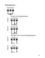
Страница 37: ... 53 51 52 23 21 22 11 12 13 43 41 42 Connexions Alimentation Voie 1 Voie 2 Voie 2 Voie 1 Sorties vers la zone dangereuse Zone non dangereuse Tension cc Tension cc Alarme de boucle Alarme de boucle V Masse V Masse ...

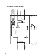
Страница 38: ...2 33 53 51 31 23 22 21 43 41 V reg 13 12 11 20 Ω Sortie Alimentation Alimentation Voie 1 Voie 2 SCHEMA DE PRINCIPE Barrière SI 24 230 Vca 24 250 Vcc Sortie Limitation 3 8 et 20 5 mA Komp Rel Relais commun Relæ N O Relais N F ...

Страница 39: ...tverzeichnis Warnung 38 Sicherheitsregeln 39 EG Konformitätserklärung 41 Zerlegung des SYSTEMs 5000 42 Verwendung 43 Technische Merkmale 43 Montage Installation 43 Anwendungen 44 Bestellangaben 45 Elektrische Daten 45 Anschlüsse 47 Blockdiagramm 48 ...

Страница 40: ... die Schutzeinrichtungen des Moduls be einträchtigt WARNUNG Vor dem abgeschlossenen festen Einbau des Moduls darf daran keine gefährliche Spannung angeschlossen werden und folgende Maßnahmen sollten nur in spannungslosem Zustand des Moduls und unter ESD sicheren Verhältnisse durchgeführt werden Öffnen des Moduls zum Einstellen von Umschaltern und Überbrückern Installation Montage und Demontage von...

Страница 41: ...vertretbar ist Bedienungspersonal sind Personen die im Normalbetrieb mit dem Produkt die Drucktasten oder Potentiometer des Produktes einstellen bzw bedienen und die mit dem Inhalt dieses Handbuches vertraut gemacht wurden Empfang und Auspacken Packen Sie das Modul aus ohne es zu beschädigen und sorgen Sie dafür dass das Handbuch stets in der Nähe des Moduls und zugänglich ist Die Verpackung sollt...

Страница 42: ...ugänglich und nahe am Modul angebracht sein Der Unterbrecherschalter soll derart gekennzeichnet sein dass kein Zweifel darüber bestehen kann dass er die Spannung für das Modul unterbricht Das Produktionsjahr ist an den ersten zwei Ziffern der Serien nummer abzulesen Kalibrierung und Justierung Während der Kalibrierung und Justierung sind die Messung und der Anschluss externer Spannungen entspreche...

Страница 43: ...ehe die Elektrische Daten des Moduls Die Niederspannungsrichtlinien 2006 95 EG und nachfolgende Änderungen EN 61010 1 Die ATEX Richtlinien 94 9 EG und nachfolgende Änderungen EN 50014 1997 E inkl A1 A2 EN 50020 2002 E und EN 50281 1 1 1998 inkl A ATEX Zertifikat DEMKO 99ATEX126256 Änderungen zur Einhaltung der folgenden Nachfolgenormen sind nicht erforderlich EN 60079 0 2009 und EN 60079 11 2012 Z...

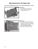
Страница 44: ...ennen Abbildung 1 Das Modul wird von der DIN Schiene gelöst indem man den unteren Verschluss löst Abbildung 2 Die Platine wird daraufhin heraus genommen indem man den oberen Verschluss anhebt und gleichzeitig die Frontabdeckung heraus zieht Jetzt können Schalter und Überbrücker verändert werden ...

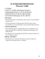
Страница 45: ...triebssicherer Gleichrichtung der aktiven Stromschleife von 2 Leiter Signalgebern in explosionsgefährdeten Bereichen Technische Merkmale PR5420B besitzt Relais mit Wechselschaltern auf der ungefährdeten Seite Wenn der Schleifenstrom innerhalb der festgesetzten Grenze liegt ist das Relais gezogen Die Versorgung und die Ausgänge sind galvanisch voneinander getrennt und nicht mit Masse verbunden Mont...

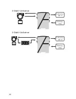
Страница 46: ...44 Schleifen alarm Schleifen alarm Versorg ung Versorg ung 2 Draht Umformer 2 Draht Umformer ...

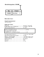
Страница 47: ...peratur 20 28 C Leitungsquerschnitt max 1 x 2 5 mm2 Litzendraht Klemmschraubenanzugsmoment 0 5 Nm Relative Luftfeuchtigkeit 95 RF nicht kond Abmessungen HxBxt 109 x 23 5 x 130 mm DIN Schiene Typ DIN 46277 Schutzart IP20 Gewicht 215 g 5420B Zweifach 2 Typ Kanal Bestellangaben 5420B EMV Immunitätseinwirkung 0 5 Erweiterte EMV Immunität NAMUR NE 21 A Kriterium Burst 1 ...

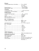
Страница 48: ...250 VRMS Imax 2 ARMS Max AC Leistung 100 VA Max Belastung bei 24 VDC 1 A EEx I S Zulassung DEMKO 99ATEX126256 II 1 GD EEx ia IIC Geeignet für Zone 0 1 2 20 21 oder 22 Ex I S Daten Um 250 V Uo 28 VDC Io 93 mADC Po 0 65 W Lo 3 mH Co 0 08 µF GOST R Zulassung VNIIM VNIIFTRI Cert no Siehe www prelectronics de Eingehaltene Richtlinien Norm EMV 2004 108 EG EN 61 326 1 LVD 2006 95 EG EN 61010 1 PELV SELV ...

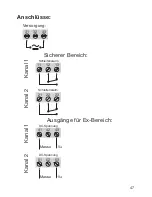
Страница 49: ... 32 33 53 51 52 23 21 22 11 12 13 43 41 42 Anschlüsse Versorgung Ausgänge für Ex Bereich DC Spannung DC Spannung Kanal 1 Kanal 2 Kanal 2 Schleifenalarm Sicherer Bereich Kanal 1 Schleifenalarm V Masse V Masse ...

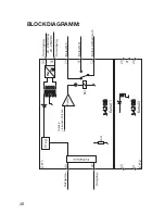
Страница 50: ...H 2 33 53 51 31 23 22 21 43 41 V reg 13 12 11 20 Ω Versorgung Versorgung Kanal 1 Kanal 2 BLOCKDIAGRAMM 24 230 VAC 24 250 VDC Ex Barriere Ausgang Ausgang Grenze 3 8 und 20 5 mA Komp Rel Relais gemeinsam Relais N O Relais N C ...

Страница 51: ...lators for analogue and digital signals as well as HART signals A wide product range with both loop powered and universal isolators featuring linearisation inversion and scaling of output signals PC or front programmable modules with universal options for input output and supply This range offers a number of advanced features such as process calibration linearisation and auto diagnosis A wide sele...

Страница 52: ...sales prelectronics it www prelectronics se sales prelectronics se www prelectronics co uk sales prelectronics co uk www prelectronics com sales prelectronics com www prelectronics cn sales prelectronics cn Head office Denmark www prelectronics com PR electronics A S sales prelectronics dk Lerbakken 10 tel 45 86 37 26 77 DK 8410 Rønde fax 45 86 37 30 85 ...

Отзывы: