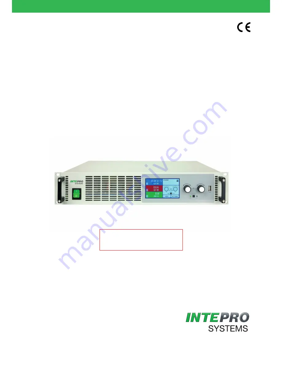
background image

PSI 9000 2U Series

DC Laboratory Power Supply

THE POWER TEST EXPERTS

User Manual

Attention! This document is only valid for devices with 

firmware “KE: 2.09” and “HMI: 2.01” and “DR: 1.6.3” or 

higher. For availability of updates for your device check 

our website or contact us.

www.InteproATE.com      Version 2   July 2016

Summary of Contents for PSI 9000 2U Series

Page 1: ...WER TEST EXPERTS User Manual Attention This document is only valid for devices with firmware KE 2 09 and HMI 2 01 and DR 1 6 3 or higher For availability of updates for your device check our website o...

Page 2: ......

Page 3: ...ing 37 2 3 8 Installation of an AnyBus interface module 38 2 3 9 Connecting the analog interface 38 2 3 10 Connecting the Share bus 39 2 3 11 Connecting the USB port rear side 39 2 3 12 Initial commis...

Page 4: ...77 3 10 1 Parallel operation in master slave mode MS 77 3 10 2 Series connection 80 3 10 3 Two quadrant operation 2QO 81 4 SERVICEAND MAINTENANCE 4 1 Maintenance cleaning 83 4 2 Fault finding diagnos...

Page 5: ...16 PSI 9200 25 2U 06230310 PSI 9500 20 2U 06230317 Changes and modifications for special models will be listed in a separate document 1 1 4 Symbols and warnings Warning and safety notices as well as g...

Page 6: ...model in frame for wall mounting Maximum current of the device in Ampere Maximum voltage of the device in Volt Series 8 Series 8000 or 800 9 Series 9000 Type identification PS Power Supply usually pr...

Page 7: ...electronic loads do not connect power sources to equipment under power sparking may occur which can cause burns as well as damage to the equipment and to the source ESD regulations must be applied whe...

Page 8: ...d cleaning of the equipment ensure that all employees who use the equipment have read and understood the manual Furthermore the users are to be regularly schooled in working with the equipment and the...

Page 9: ...uld be damaged Signal OCP OverCurrent Shutdown of the DC output due to excess of the preset limit Non critical protects the load from excessive current consumption Signal OPP OverPower Shutdown of the...

Page 10: ...ature coefficient for set values K Voltage current 100 ppm Voltage regulation Adjustment range 0 40 V 0 80 V 0 200 V Accuracy 1 at 23 5 C 0 1 UNom 0 1 UNom 0 1 UNom Stability at 10 UAC 0 02 UNom 0 02...

Page 11: ...s signals CV OVP OT CV OVP OT CV OVP OT Galvanic isolation to the device Max 1500 V DC Max 1500 V DC Max 1500 V DC Insulation Output DC to enclosure PE DC minus permanent max 400 V DC plus permanent m...

Page 12: ...ensation Max 5 UNom Max 5 UNom Max 5 UNom Output voltage fall time at no load after switching DC output off Down from 100 to 60 V less than 10 s Current regulation Adjustment range 0 10 A 0 6 A 0 4 A...

Page 13: ...not condensing Standards EN 61010 EN 61326 Overvoltage category 2 Protection class 1 Pollution degree 2 Operational altitude 2000 m Digital interfaces Featured 1x USB B for communication 1x USB A for...

Page 14: ...tion range 0 1650 W 0 1650 W 0 1650 W Temperature coefficient for set values K Voltage current 100 ppm Voltage regulation Adjustment range 0 40 V 0 80 V 0 200 V Accuracy 1 at 23 5 C 0 1 UNom 0 1 UNom...

Page 15: ...s signals CV OVP OT CV OVP OT CV OVP OT Galvanic isolation to the device Max 1500 V DC Max 1500 V DC Max 1500 V DC Insulation Output DC to enclosure PE DC minus permanent max 400 V DC plus permanent m...

Page 16: ...MS 190 mVPP 48 mVRMS 212 mVPP 60 mVRMS Remote sensing compensation Max 5 UNom Max 5 UNom Max 5 UNom Output voltage fall time at no load after switching DC output off Down from 100 to 60 V less than 10...

Page 17: ...not condensing Standards EN 61010 EN 61326 Overvoltage category 2 Protection class 1 Pollution degree 2 Operational altitude 2000 m Digital interfaces Featured 1x USB B for communication 1x USB A for...

Page 18: ...tection range 0 3300 W 0 3300 W 0 3300 W Temperature coefficient for set values K Voltage current 100 ppm Voltage regulation Adjustment range 0 40 V 0 80 V 0 200 V Accuracy 1 at 23 5 C 0 1 UNom 0 1 UN...

Page 19: ...us signals CV OVP OT CV OVP OT CV OVP OT Galvanic isolation to the device Max 1500 V DC Max 1500 V DC Max 1500 V DC Insulation Output DC to enclosure PE DC minus permanent max 400 V DC plus permanent...

Page 20: ...mVRMS 190 mVPP 48 mVRMS 212 mVPP 60 mVRMS Remote sensing compensation Max 5 UNom Max 5 UNom Max 5 UNom Output voltage fall time at no load after switching DC output off Down from 100 to 60 V less tha...

Page 21: ...ot condensing Standards EN 61010 EN 61326 Overvoltage category 2 Protection class 1 Pollution degree 2 Operational altitude 2000 m Digital interfaces Featured 1x USB B for communication 1x USB A for f...

Page 22: ...hange without notice A Mains switch D Exhausts G AC input fuse B Control panel E Share Bus and remote sensing connectors H AC input connector C Control interfaces digital analog F DC output terminal t...

Page 23: ...23 PSI 9000 2U Series PSI 9000 2U Series DC Laboratory Power Supply User Manual Figure 3 Left hand side with DC terminal type 1 Figure 4 Right hand side with DC terminal type 2...

Page 24: ...24 PSI 9000 2U Series 2015 Intepro Systems LP Specifications subject to change without notice Figure 5 View from above with DC cover terminal type 1...

Page 25: ...selection of the decimal position to be changed cursor in the current value selection Right knob turn adjusting the current power or resistance set value or setting parameter values in the menu Right...

Page 26: ...nnected to standard industrial buses simply by chang ing or adding a small module The configuration if necessary at all is simple Thus the power supplies may for example be operated with other power s...

Page 27: ...d in separate documentation It is usually avail able on the CD which is included with the device or as a PDF download from the Intepro Systems website 1 9 5 Options These options are usually ordered a...

Page 28: ...the variable internal resistance is only displayed by active resistance mode When the DC output is switched on the actual regulation mode CV CC CP or CR is displayed next to the cor responding actual...

Page 29: ...a as long as it s not locked The display changes to The physical units below the depiction of the knobs shows the current as signment On a power supply the left knob is always assigned to the voltage...

Page 30: ...is intended for connecting a standard USB flash drive This can be used for Loading or saving sequences for the arbitrary and loading tables for the UI IU function generator Updating HMI firmware new...

Page 31: ...iption 35400100 IF AB CANO CANopen 1x Sub D 9pole male 35400101 IF AB RS232 RS 232 1x Sub D 9pole male null modem 35400103 IF AB PBUS Profibus DP V1 Slave 1x Sub D 9pole female 35400104 IF AB ETH1P Et...

Page 32: ...ed to the load The maximum possible compensation is given in the technical specifications 1 9 12 Master Slave bus Another port is provided on the backside of the device comprised of two RJ45 sock ets...

Page 33: ...dly way 2 1 3 Storage In case of long term storage of the equipment it is recommended to use the original packaging or similar Storage must be in a dry environment If possible seal in packaging to avo...

Page 34: ...cross section should be increased and the cable length reduced 2 3 3 Installing the device Select a location for the device that makes the connection to the load as short as possible Leave a minimum...

Page 35: ...d heavy DC connection cable it is necessary to consider the weight of the cable and the strain imposed on the DC connection A strain reliever should be used when mounted in a 19 cabinet or similar whe...

Page 36: ...n series connection with others it is always only allowed to ground one of the DC output poles The following must be considered Because of limitations with the isolation a max potential shift of 400 V...

Page 37: ...ength Recommendation for cables up to 5 m use at least 0 5 mm Sense cables should be twisted and laid close to the DC cables to damp oscillation If neces sary an additional capacitor should be install...

Page 38: ...ensures correct alignment When inserting take care that it is held as close as possible to a 90 angle to the rear wall of the device Use the green PCB which you can recognize on the open slots as a g...

Page 39: ...ition the USB equipment will first be listed in the Windows Device Manager as other hardware Windows 7 and the driver may possibly not be fully installed In this case take the following steps In Devic...

Page 40: ...output power according to P UOUT IOUT reaches the adjusted current or power limit In both cases the device will automatically change to constant current or constant power operation whichever occurs f...

Page 41: ...2500 W The derating only affects the power stages so the full range for power set value adjustment remains though the device will switch earlier to constant power operation In this situation constant...

Page 42: ...evice causes it to stop supplying power temporarily After cooling down the device will automatically continue to supply power while the condition of the DC output remains and the alarm doesn t require...

Page 43: ...stored either on or off All set values are always saved and restored 3 4 2 Switching off the device On switch off the last output condition and the most recent set values are saved Furthermore a PF al...

Page 44: ...D 0V Unom Aktion NO SIGNAL WARNING ALARM UCD 0A Inom Aktion NO SIGNAL WARNING ALARM OCD 0A Inom Aktion NO SIGNAL WARNING ALARM OPD 0W Pnom Aktion NO SIGNAL WARNING ALARM Default Profile User Profile 1...

Page 45: ...Sequence 1 DIN Sequence 2 DIN Sequence 3 DIN Sequence 4 DIN Sequence 5 DIN Repetition Seq cycles 0 999 Time t1 0 1ms 36000s Us AC 0V Umax Ue AC 0V Umax fs 1 T 0Hz 10000Hz fe 1 T 0Hz 10000Hz Angle 0 3...

Page 46: ...name Configure English Backlight Setup Panel Contrast Deutsch Language Always on Off after 60 sec Brightness 1 10 HMI Lock Lock all ON OFF possible Key Sound Sound on Sound off Alarm Sound Sound on S...

Page 47: ...C output after power ON 3 Determines the condition of the DC output after power up OFF DC output is always off after switching on the device Restore DC output condition will be restored to the conditi...

Page 48: ...d For all Ethernet interfaces with two ports P1 is related to port 1 and P2 to port 2 like printed on the module face Two port interfaces will use one IP only IF Level 1 Level 2 Level 3 Description Et...

Page 49: ...DNS 1 Here the addresses of the first and second Domain Name Servers DNS can be defined if needed A DNS is only necessary if the device has Internet access and should call Internet URLs e g an intern...

Page 50: ...ting it with ENTER button Only one can be disabled 3 4 3 8 Menu HMI settings These settings refer exclusively to the control panel HMI Element Description Language Selection of the display language Cu...

Page 51: ...value P max to 1 00 kW while the currently adjusted power set value is 2 00 kW then the set value first would have to be reduced to 1 00 kW or less 3 4 5 Changing the operating mode In general the ma...

Page 52: ...for 1 5 seconds next to the adjusted value How to adjust values with the rotary knobs 3 First check whether the value to be changed is assigned to one of the rotary knobs The main screen displays the...

Page 53: ...long as the control panel is not fully locked press the button ON OFF Otherwise you are asked to dis able the HMI lock first 2 This button toggles between on and off as long as a change is not restric...

Page 54: ...the lock can be useful if the device is remotely controlled by software or some electronic device but it is required to make adjustments at the device or deal with emergency which would not be possib...

Page 55: ...hresholds cannot be set through the AI and there fore must be adapted to the given situation before the AI is put in operation Analog set values can be fed in by an external voltage or generated by th...

Page 56: ...als For control and status signals 5 REMOTE DI Switching internal remote control Remote LOW ULow 1 V Internal HIGH UHigh 4 V Internal Open Voltage range 0 30 V IMax 1 mA bei 5 V ULOW to HIGH typ 3 V R...

Page 57: ...is is also available without remote control being active It is recommended that a low resistance contact such as a switch relay or transistor is used to switch the pin to ground DGND Following situati...

Page 58: ...ol to be activated Pin Remote LOW The set values PSEL and CSEL are generated from for example the reference voltage VREF using potentiometers for each The power supply can selectively work in current...

Page 59: ...a pop up in the middle of the display and if activated an acoustic signal to make the user aware The alarm must always be acknowledged How to acknowledge an alarm in the display 1 If the alarm is ind...

Page 60: ...exceeds the de fined threshold 0 V UNom UCD UnderCurrent Detection Triggers an event if the output current falls below the defined threshold 0 A INom OCD OverCurrent Detection Triggers an event if th...

Page 61: ...ing a user profile The menu Profiles serves to select between a default profile and up to 5 user profiles A profile is a collection of all settings and set values Upon delivery or after a reset all 6...

Page 62: ...not available 3 9 2 General 3 9 2 1 Limitations The function generator is not accessible for manual access nor remote control if master slave mode has been activated and the device was configured as...

Page 63: ...ch you can access with touch area When entering function generator mode limits which can prevent the function from working are reset to safe values For example if you apply the selected function to th...

Page 64: ...of U I A Amplitude of the signal to be generated I Off U Off A Nominal value A of U I Off Offset based on the zero point of the mathematic sine curve may not be smaller than the amplitude f 1 t 1 1000...

Page 65: ...I A U A 0 Nominal value Off von U I A Amplitude of the signal to be generated I Off U Off 0 Nominal value A von U I Off Offset based on the foot of the rectangular wave t1 0 1 ms 36000 s Time pulse wi...

Page 66: ...on the curve defined in DIN 40839 EN ISO 7637 test impulse 4 and is only applicable to voltage It replicates the progress of automobile battery voltage during engine starting The curve is divided int...

Page 67: ...art of the curve AC Is DC Is AC Nominal value Is AC of I 1 100 Start value of the DC part of the curve Ie DC Ie AC Nominal value Ie AC of I 1 100 End value of the DC part of the curve Seq time 0 1 ms...

Page 68: ...so with each new half sine wave Additionally the first sine wave starts with a negative half wave be cause the angle is set at 180 The start angle can be shifted at will in 1 steps between 0 and 359 S...

Page 69: ...t the end offset DC is higher than the start the second sequence run will revert to the same start level as the first regardless of the values achieved at the end of the first run This can produce a d...

Page 70: ...ange A AC Start 0 50 U or I B AC End 0 50 U or I C Frequency Start 0 1000 Hz D Frequency End 0 1000 Hz E Start angle AC 0 359 F DC Start 0 Nominal value of U or I AC Start G DC End 0 Nominal value of...

Page 71: ...rt levels at the beginning of the ramp It is recommended that these values are set equal to those in A start unless the load at the DC output should not be provided with voltage before the start of th...

Page 72: ...which the table is being loaded The file must be a text file of type Excel CSV semicolon as separator and must only contain one column with exactly 4096 values without gaps Values with decimal places...

Page 73: ...urer for an evaluation In case option HS is installed in the device see 1 9 5 Options the result of operating critical inverters can be optimized 3 9 13 3 Usage In the PV table function which is based...

Page 74: ...e on screen instructions The table can be used to analyze the values or to visualize it in Excel or similar tools How to work with the PV table function 1 With an appropriate load connected for exampl...

Page 75: ...e freely modified as long as P3 s voltage is lower than the one of P2 and P3 s current is higher than the one of P2 How to configure the FC table 1 In the function generator menu tap on then and then...

Page 76: ...al commands is different from manual operation The external documentation Programming Guide ModBus SCPI explains the approach In general the following apply The function generator is not controllable...

Page 77: ...t in the parallel operation is simply connected to the next unit using cables with cross section according to the maximum current and with short as possible length 3 10 1 2 Wiring the Share bus The Sh...

Page 78: ...ice 4 Accept the settings with the touch area and return to the main page The slave is then configured for master slave Repeat the procedure for all of the other slave units Step 2 Configuring the mas...

Page 79: ...on to any slave will result in shutdown of all DC outputs as a safety measure and the master will report this situation in the display with a pop up Master slave safety mode Then the MS system has to...

Page 80: ...ly regarding set values and DC output status whether manually controlled or in digital remote control According to the limit of the potential shift that comes with series connection units with a certa...

Page 81: ...preferably be in operating mode CV The load will then using the Share Bus control the output voltage of the power supply Typical applications Fuel cells Capacitor tests Motor driven applications Elect...

Page 82: ...3500 W USet 24 V and UVD 20 V or any other minimum value to which the battery shall be discharged to Assumption battery has a voltage of 26 V at test start DC input s and DC output s of all units swi...

Page 83: ...Contact Intepro Systems for the steps to be taken It may be necessary to return the device to Intepro Systems with or without guarantee If a return for checking or repair is to be carried out ensure...

Page 84: ...our device or contain new features The firmware of the device if necessary is updated via the rearside USB port For this a software a so called update tool is needed which is available from Intepro Sy...

Page 85: ...ith a max error of half the PSI s voltage error That measure ment device can also be used to measure the shunt voltage when readjusting the current If the current is also going to be calibrated a suit...

Page 86: ...he shunt Enter it using the keypad assure yourself the value is correct and submit with ENTER 5 Repeat step 4 for the next three steps total of four steps If you are using the remote sensing feature i...

Page 87: ...and customer will be carried out by Intepro Systems For this the device must be returned to Intepro Systems No RMA number is needed It is sufficient to package the equip ment adequately and send it t...

Page 88: ...86 sales inteproate com www inteproate com United Kingdom Intepro UK Ltd 9 Lakeside Business Park Swan Lane Sandhurst Berkshire GU47 9DN UK Tel 44 012 5287 5600 China Intepro Power Block 7 Fourth Indu...

Reviews: