background image

Chapter 5 Function parameter 

95 


Ch
ap

ter 5


AI2 

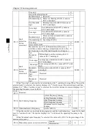
Panel potentiometer 

Analog input range 100% corresponds to F7.44 

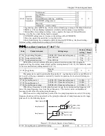
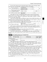
F7.44  Timing run time 

0.0Min~6500.0Min 

0.0Min 


The group of parameters are used to complete the inverter timing run function. 
If F7.42 timing function is active, the inverter starts as the timer starts, when the set timing 

run time is reached, the inverter automatically shut down, at the same time the multi-function DO 
will output ON signal. 

Every time the inverter starts, the timer will time from 0, the remaining time can be viewed 

by d0.20. The timing run time is set by F7.43, F7.44 in minute. 

F7.45  Current running arrival time.  0.0Min~6500.0Min 

0.0Min 


When current running time reaches this time, the inverter multi-function digital DO will 

output"Current Running Time Arrival "ON signal. 

F7.46  Awakens frequency 

dormancy frequency (F7.48)~ to 
maximum frequency (F0.19) 

0.00Hz 


F7.47  Awakens delay time 

0.0s~6500.0s 

0.0s 


F7.48  Dormancy frequency 

0.00Hz~ awakens frequency (F7.46) 

0.00Hz 


F7.49  Dormancy delay time 

0.0s~6500.0s 

0.0s 


F7.50 

AI1 input voltage protection 
lower limit 

0.00V~F7.51 

3.10V 


F7.51 

AI1 input voltage 
protection upper limit 

F7.50~10.00V 

6.80V 


When analog AI1 input is greater than F7.51, or when AI1 input is less than F7.50, the 

inverter multi-functional DO will output "AI1 input overrun"signal, so as to indicate whether the 
AI1 input voltage is within the set range or not. 

F7.52   

F7.53 

Reserve 


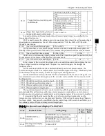
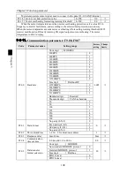
F7.54  Jog mode setting 

Bits 

Jog direction 

002 


Forward 

reverse 

Determine the direction from the main 
terminal 

Ten bits 

End running state by Jogging 

Restore to the state before jogging 

stop running 

Hundred 
bits 

Acceleration/deceleration time after 
stop jogging 

Recover to the      acceleration/deceleration 
time before jogging 

Keep the acceleration/deceleration time when 
jogging 

5-2-10.

Fault and protection:F8.00-F8.35 

Code  Parameter name 

Setting range 

Factory 
setting 

Change 
limits 

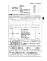
F8.00  Overcurrent stall gain 

0~100 

20 


F8.01 

Overcurrent stall protection 
current 

100%~200% 

150% 


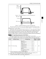
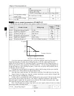
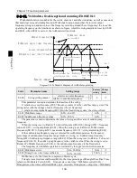
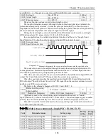
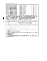
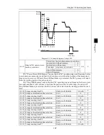
When the inverter output current reaches the set current stall protection current (F8.01), the 

inverter reduces the output frequency in the acceleration or constant speed operation, while the 
slow down speed, until the current is less than the current (F8.01). 

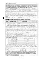
Overcurrent stall gain is used for adjusting inhibition overcurrent capability during 

Содержание PI500 series

Страница 1: ...frequency converter please carefully read this manual before installing it For any problem when using this product please contact your local dealer authorized by this company or directly contact this...

Страница 2: ...oning 15 4 1 Use of the environment 15 4 2 Installation direction and space 15 4 3 Wiring Diagram 16 4 4 Main circuit terminal 18 4 5 Control circuit terminals 21 4 6 Wiring Precautions 24 4 7 Spare C...

Страница 3: ...y1 00 y1 30 119 Chapter 6 Troubleshooting 122 6 1 Fault alarm and countermeasures 122 6 2 EMC Electromagnetic Compatibility 126 6 3 EMC directive 127 Chapter 7 Dimension 129 7 1 Dimension 129 Chapter...

Страница 4: ...Appendix III How to use universal encoder expansion card 157 Appendix IV CAN bus communication card use description 159 Appendix V Instruction of Profitbus DP communication card 160...

Страница 5: ...k the nameplate on the side of the frequency inverter to ensure that the product you have received is right the one you ordered 1 1 1 Instructions on nameplate Input Source Spec Output Power Spec Prod...

Страница 6: ...less vibration avoid direct sunlight When two or more converters are installed in a cabinet please pay attention to the installation location ensure the good heat dissipation effect When wiring Danger...

Страница 7: ...ause burns Non professional personnel is not allowed to detect signal when operating Doing so may cause personal injury or damage to this unit Note When the inverter is operating you should avoid that...

Страница 8: ...inverter should be turned on off without output status otherwise which easily lead to damage to the inverter module 8 Use other than the ratedvoltage PI series inverter is not suitable for use beyond...

Страница 9: ...ged fully otherwise there is a danger of electric shock 3 Body static electricity will seriously damage the internal MOS field effect transistors etc if there are not anti static measures do not touch...

Страница 10: ...0 430 426 220 PI500 250F3 250 468 465 250 PI500 250G3 PI500 280F3 250 280 468 525 465 520 250 280 PI500 280G3 PI500 315F3 280 315 525 590 520 585 280 315 PI500 315G3 PI500 355F3 315 355 590 665 585 65...

Страница 11: ...the control terminal Built in PID Easy to realize closed loop control system for the process control Automatic voltage regulation AVR Automatically maintain a constant output voltage when the voltage...

Страница 12: ...ed pulse output 0 to 100kHz square wave one relay output terminal 2 analog output terminals respectively for optional range 0 to 20mA or 0 to 10V they can be used to set frequency output frequency spe...

Страница 13: ...485 communication module can communicate with the host computer Environment Product standard Environment temperature 10 to 40 temperature at 40 to 50 please derating for use Storage temperature 20 to...

Страница 14: ...erminal operation and remote operation communication control ON terminal control working status OFF keyboard control working status Flashing remote control working status FWD REV Forward reverse runni...

Страница 15: ...ontrol status Stomp Reset Key For stopping running in the running status for resetting the operation in fault alarm status The function of the key is subject to F6 00 Running key For starting running...

Страница 16: ...on Second level menu display Third level menu display Diagram 3 2 Operation processes Description Back to the level 2 menu from level 3 menu by PRG key or ENTER key in the level 3 operation status Th...

Страница 17: ...tus DO output status analog input AI1 voltage analog input AI2 voltage panel potentiometer input voltage Actual count value Actual length value linear speed PID settings and PID feedback etc their dis...

Страница 18: ...disengage its load please select 2 asynchronous motor parameter comprehensive auto turning for b0 27 and then press the RUN key on the keyboard panel the inverter will automatically calculate the mot...

Страница 19: ...mbustible explosive gas liquid or solid 4 2 Installation direction and space PI500 series inverter according to different power rating the requirements of around installation reserve space is differen...

Страница 20: ...wind Diagram 4 2 Heat insulation deflector up and down installation diagram 4 3 Wiring Diagram Frequency inverter wiring is divided by main circuit and control circuit Users must properly connect freq...

Страница 21: ...Chapter 4 Installation and commissioning 17 Chapter 4 4 3 1 Wiring diagramv Main circuit Control circuit Diagram 4 3 Wiring diagram...

Страница 22: ...W G3 main circuit terminal Diagram 4 4 7 5kW 15kW G3 main circuit terminal 2 18 5kW 22kW G3 main circuit terminal Diagram 4 5 18 5kW 22kW G3 main circuit terminal 3 30kW 37kW G3 main circuit terminal...

Страница 23: ...apter 4 5 93kW 110kW G3 main circuit terminal Diagram 4 8 93kW 110kW G3 6 132kW main circuit terminal 132G3 160F3 Diagram 4 9 132kW G3 main circuit terminal 7 160kW 220kW G3 main circuit terminal Diag...

Страница 24: ...f external DC reactor is connected firstly disconnect and then reconnect 4 4 2 Function description of main circuit terminal Terminal Name Explain R Inverter input terminals Connect to three phase pow...

Страница 25: ...als and external sensor Maximum output current 200mA PLC External power input terminal When external signal is used to drive please unplug PLC jumpers PLC must be connected to external power supply an...

Страница 26: ...olar open collector output Output voltage range 0V to 24V output current range 0mA to 50mA SPB COM Digital output 2 SPB COM High speed pulse output Subject to function code F2 00 SPB terminal output m...

Страница 27: ...requency converter Dry contact mode 24V COM PLC Default DI1 DI8 COM PLC PE Shielded cable External contactor Inverter Inner power supply with main connect 24V COM PLC Default DI1 DI8 COM PLC PE Shield...

Страница 28: ...otection Do not connect power supply to U V W terminals otherwise which may cause damage to the inverter Do not directly connect braking resistor to DC bus P terminals otherwise which may cause a fire...

Страница 29: ...n 10 ohms otherwise the leakage current will occur The specifications on wires used by the main circuit wiring shall comply with the relevant provisions of the National Electrical Code The motor s cap...

Страница 30: ...elf learning Commission ing Select control manner setting F0 00 Set b0 00 b0 05 b0 28 etc Set b0 00 b0 05 Select appropriate ac deceleration time Set F0 13 F0 14 Select appropriate ac deceleration tim...

Страница 31: ...ing function parameters Code Parameter name Functional Description d0 Monitoring function group Monitoring frequency current etc F0 Basic function group Frequency setting control mode acceleration and...

Страница 32: ...output power 0 1kW 6 d0 06 output torque Motor output torque percentage 0 1 7 d0 07 DI input status DI input status 8 d0 08 DO output status DO output status 9 d0 09 AI1 voltage V AI1 input voltage v...

Страница 33: ...etting source 0 01Hz 29 d0 29 Command torque Observe the set command torque under the torque control mode 0 1 30 d0 30 Reserve 31 d0 31 Synchro rotor position Synchro rotor position angle 0 0 32 d0 32...

Страница 34: ...0 to 150 100 49 F0 07 Frequency source superimposed selection Units digit frequency source selection Tens digit arithmetic relationship of master and auxiliary for frequency source 00 50 F0 08 Freque...

Страница 35: ...1 YES 0 60 F0 18 Carrier Frequency 0 5kHz to 16 0kHz Depends on models 61 F0 19 Maximum output frequency 50 00Hz to 320 00Hz 50 00Hz 62 F0 20 Upper limit frequency source 0 F0 21 setting 1 AI1analog q...

Страница 36: ...OWN change rate 0 001Hz s to 65 535Hz s 1 000Hz s 82 F1 12 Minimum input for AIC1 0 00V to F1 14 0 00V 83 F1 13 F1 12corresponding setting 100 00 to 100 0 0 0 84 F1 14 Maximum input for AIC1 F1 12 to...

Страница 37: ...32 AI2 filter time 0 00s to 10 00s 0 10s 103 F1 33 AI3 filter time 0 00s to 10 00s 0 10s 104 F1 34 HDI Filter time 0 00s to 10 00s 0 00s 105 F1 35 DI terminal valid mode selection 1 Units digit DI1 0...

Страница 38: ...y output function selection 0 to 40 0 119 F2 02 Relay 1 output function selection TA1 TB1 TC1 2 120 F2 03 Undefined 121 F2 04 SPA output function selection collector open circuit output terminals 1 12...

Страница 39: ...7 F3 00 Start up mode 0 Direct startup 1 Speed tracking restart 2 Pre excitation start AC asynchronous motor 0 138 F3 01 Speed tracking mode 0 2 reserve 3 Rotate speed tracking method3 3 139 F3 02 Spe...

Страница 40: ...int 1 0 0 to 100 0 0 0 158 F4 05 Multipoint V F frequency point 2 F4 03 to F4 07 0 00Hz 159 F4 06 Multipoint V F voltage point 2 0 0 to 100 0 0 0 160 F4 07 Multipoint V F frequency point 3 F4 05 to b0...

Страница 41: ...roportional gain 0 to 60000 2000 183 F5 15 Torque regulator integral gain 0 to 60000 1300 5 1 8 F6 Group Keyboard and display No Code Parameter name Setting range Factory setting Chan ge 184 F6 00 STO...

Страница 42: ...button valid 0 202 F6 21 QUICK key function selection 0 no function 1 Jog running 2 Shift switch display state 3 FWD RVS switchover 4 Clear up UP DOWN setting 5 Free stop 6 running command given in s...

Страница 43: ...tion deadband 0 00s to 3600 0s 0 00s 220 F7 17 Reverse rotation control 0 Enable 1 Disable 0 221 F7 18 Set frequency lower than lower limit frequency mode 0 running at lower limit frequency 1 stop 2 z...

Страница 44: ...36 Random arrivals current 1 0 0 to 300 0 rated motor current 100 240 F7 37 Random arrivals current 1 width 0 0 to 300 0 rated motor current 0 0 241 F7 38 Random arrivals current 2 0 0 to 300 0 rated...

Страница 45: ...bits 0 recover to the previous deceleration time after jogging 1 keep the deceleration time the sameafter jogging 002 5 1 10 F8 Group Fault and protection No Code Parameter name Setting range Factory...

Страница 46: ...ed deviation 0 0 to 50 0 maximum frequency 20 0 273 F8 16 Detection time for too large speed deviation 0 0 to 60 0s 5 0s 274 F8 17 Fault protection action selection 1 Units digit Motor overload Err 11...

Страница 47: ...ncy to run if the load drop does not happen automatically restore to the set frequency for when the load drop does not happen Ten thousands digit PID feedback loss when running Err 31 same as F8 17 un...

Страница 48: ...value 0 200 110 290 F8 35 motor over heat alma value 0 200 90 5 1 11 F9 Group Communication parameter No Code Parameter name Setting range Factory setting Chan ge 291 F9 00 Baud rate Units digit MODBU...

Страница 49: ...ol acceleration time 0 00s to 650 00s 0 00s 303 FA 04 Torque control deceleration time 0 00s to 650 00s 0 00s 304 FA 05 Torque control forward maximum frequency 0 00Hz to F0 19 maximum frequency 50 00...

Страница 50: ...ge Factory setting Chan ge 320 E0 00 Swing setting manner 0 relative to center frequency 1 relative to maximum frequency 0 321 E0 01 Wobbulate range 0 0 to 100 0 0 0 322 E0 02 Sudden jump frequency ra...

Страница 51: ...100 0 to 100 0 0 0 346 E1 14 14 stage speed setting 14X 100 0 to 100 0 0 0 347 E1 15 15 stage speed setting 15X 100 0 to 100 0 0 0 348 E1 16 Simple PLC running mode 0 stop after single running 1 hold...

Страница 52: ...8 E1 36 9 stage running time T9 0 0s h to 6500 0s h 0 0s h 369 E1 37 9 stage ac deceleration time selection 0 to 3 0 370 E1 38 10 stage running time T10 0 0s h to 6500 0s h 0 0s h 371 E1 39 10 stage a...

Страница 53: ...nd reference 0 385 E2 01 PID keyboard reference 0 0 to 100 0 50 0 386 E2 02 PID feedback source 0 to 8 0 387 E2 03 PID action direction 0 positive 1 negative 0 388 E2 04 PID setting feedback range 0 t...

Страница 54: ...ntinue 1 stop 00 407 E2 23 PID initial value 0 0 to 100 0 0 0 408 E2 24 PID initial value hold time 0 00s to 360 00s 0 00s 409 E2 25 Maximum deviation of twice outputs forward 0 00 to 100 00 1 00 410...

Страница 55: ...selection of DI 0 to 50 0 425 E3 08 AI2 terminal as a function selection of DI 0 to 50 0 426 E3 09 Panel potentiometer as a function selection of DI 0 to 50 427 E3 10 AI as DI effective mode selection...

Страница 56: ...s 441 b0 02 Rated voltage 1V to 2000V Depends on models 442 b0 03 Rated current 0 01A to 655 35A inverter power 55kW 0 1A to 6553 5A inverter rate 55kW Depends on models 443 b0 04 Rated frequency 0 01...

Страница 57: ...EMF 0 1V to 6553 5V 454 b0 15 to b0 26 Reserve 455 b0 27 Motor parameter auto tunning 0 no operation 1 asynchronous motor parameters still auto tunning 2 asynchronous motor parameters comprehensive au...

Страница 58: ...yboard storage area 2 21 download the parameters from keyboard storage 1 area to the storage system 3 22 download the parameters from keyboard storage 2 area to the storage system 3 0 465 y0 01 User p...

Страница 59: ...tection abnormal 19 Motor self learning abnormal 20 Encoder PG card abnormal 21 Parameter read and write abnormal 22 Inverter hardware abnormal 23 Motor short to ground 24 Reserved 25 Reserved 26 Runn...

Страница 60: ...tage of the second fault 485 y1 16 Input terminal status of the second fault 486 y1 17 Output terminal status of the second fault 487 y1 18 Reserved 488 y1 19 Power on time of the second fault 489 y1...

Страница 61: ...voltage V 0 1V Detected value for DC bus voltage d0 03 Output voltage V 1V Actual output voltage d0 04 Output current A 0 01A Effective value for Actual motor current d0 05 Output power kW 0 1kW Calcu...

Страница 62: ...Feedback speed unit 0 1Hz 0 1Hz PG feedback speed to an accuracy of 0 1hz d0 20 Remaining run time 0 1Min Remaining run time display it is for timing run control d0 21 Linear speed 1m Min Show the li...

Страница 63: ...ction group F0 00 F0 27 Code Parameter name Setting range Factory setting Change Limit F0 00 Motor control mode Vector control without PG 0 2 Vector control with PG 1 V F control 2 0 Vector control wi...

Страница 64: ...ey on the keyboard or multi function input terminals UP DOWN The Inverter powers down and then powers on again the set frequency value will be recovered as F0 01 digital preset frequency value 1 Keybo...

Страница 65: ...equency F0 01 does not work user can adjust frequency by using keys or multi function input terminals UP DOWN on the keyboard adjust directly on the basis of master frequency source 2 When the frequen...

Страница 66: ...frequency 3 Switch between the frequency source master setting and the arithmetic result of master and auxiliary when multi function input terminal 18 frequency switching is invalid the frequency sour...

Страница 67: ...to correct the set frequency that is the target frequency decreases or increases on the basis of the operating frequency or the set frequency The obvious difference between two settings appears when t...

Страница 68: ...various on site PI500 provides three kinds of time unit 1 second 0 1 second and 0 01 second respectively Note when modifying the function parameters the number of decimal places that the four groups...

Страница 69: ...selects 2 the frequency resolution is 0 01Hz at this time F0 19 can be set in the range from 50 00Hz to 320 00Hz F0 20 Upper limit frequency source Upper limit frequency source F0 21 setting 0 0 AI1...

Страница 70: ...n 0 51 0 F1 08 Undefined F1 09 Undefined These parameters are used to set the digital multi function input terminal the optional functions are shown in the following table Set value Function Descripti...

Страница 71: ...the frequency reference is the digital frequency this terminal is used to clear the changed frequency value by terminal UP DOWN or keyboard UP DOWN so that the reference frequency can recover to the s...

Страница 72: ...and preset frequency When the terminal is active the frequency source B is replaced with the preset frequency F0 01 41 Reserve 42 Reserve 43 PID parameter switching When DI terminal E2 19 1 is used t...

Страница 73: ...age speed setting 12X E1 12 ON ON OFF ON 13 stage speed setting 13X E1 13 ON ON ON OFF 14 stage speed setting 14X E1 14 ON ON ON ON 15 stage speed setting 15X E1 15 When multi speed is selected as fre...

Страница 74: ...Two wire mode 2 2 Three wire control mode 1 In the mode DIn is used as enabled terminal while DIx DIy terminal are used to control direction The terminal function is set as follows Terminals Set value...

Страница 75: ...m input for AIC1 0 00V to F1 14 0 00V F1 13 F1 12 corresponding setting 100 00 to 100 0 0 0 F1 14 Maximum input for AIC1 F1 12 to 10 00V 10 00V F1 15 F1 14 corresponding setting 100 00 to 100 0 100 0...

Страница 76: ...10 00V F1 23 F1 22 Corresponding to the set 100 00 100 0 100 0 For the function and use of curve 3 please refer to the description of curve 1 F1 24 AI curve selectio n Units digit AI1 curve selection...

Страница 77: ...n this group of functions is similar to curve 1 please refer to the description of curve 1 F1 30 DI filter time 0 000s 1 000s 0 010s Set software filter time for DI terminals status For the applicatio...

Страница 78: ...0 Keyboard potentiometer set value end point F1 43 Keyboard potentiometer setting value 0 100 00 Display keyboard potentiometer value through the keyboard potentiometer can modify Settings under monit...

Страница 79: ...he description of function code F7 25 5 Zero speed running no output when shutdown Inverter operation and the output frequency is 0 output ON signal When the drive is shut down the signal is OFF 6 Mot...

Страница 80: ...Frequency 2 reaches output Please refer to the function code F7 30 F7 31 s instructions 28 Current 1 reaches output Please refer to the function code F7 36 F7 37 s instructions 29 Current 2 reaches ou...

Страница 81: ...lue 0 Max setting length 11 The count value 0 Max count value 12 Coummunication set 0 0 100 0 13 Motor speed 0 Max output frequency correspondent speed 14 Output current 0 0A 100 0A Inverter power 55k...

Страница 82: ...8 Example 2 0 10V output will be changed to 0 5V The minimum input voltage value from the formula y1 10 F2 16 100 0 10 F2 16 calculated according to the formula F2 16 0 0 The maximum input voltage val...

Страница 83: ...equency of 0 00Hz Example 2 F0 03 0 the frequency source is set to digital reference F0 01 10 00Hz the digital set frequency is 10 00Hz F3 03 5 00Hz the start frequency is 5 00Hz F3 04 2 0s the hold t...

Страница 84: ...the process of start stop 0 Linear acceleration and deceleration The output frequency increases or decreases linearly PI500 provides four kinds of acceleration and deceleration time You can select by...

Страница 85: ...Within the time between t1 and t2 the slope of the output frequency variation is fixed i e the linear acceleration and deceleration is achieved in this interval 5 2 6 V F control parameters F4 00 F4 1...

Страница 86: ...ed It is recommended to increase this parameter when the motor works with heavy load but without enough torque The torque boost can be reduced when the load is lighter When the torque boost is set to...

Страница 87: ...e of bus voltage to avoid overvoltage fault The greater overexcitation gain the stronger the inhibitory effect For the occasions that the inverter s deceleration easily cause over pressure alarm the o...

Страница 88: ...ring PI control parameters for F5 00 and F5 01 Operating frequency is greater than the switching frequency 2 F5 05 speed in PI control parameters for F5 03 and F5 04 The speed ring PI parameters of s...

Страница 89: ...at the inverter s deceleration easily cause over pressure alarm the overexcitation gain needs to be improved But if overexcitation gain is too large which easily lead to the increase of output current...

Страница 90: ...0100 1111 After check the comparison of the binary number and the hexadecimal number the data is 0x7A4F Binary Hexadecimal 0000 0001 0010 0011 0100 0101 0110 0111 1000 1001 1010 1011 1100 1101 1110 11...

Страница 91: ...s display If the inverter is shutdown the load speed displays the speed relative to the set frequency that is the set load speed If the set frequency is 50 00Hz the load speed under the state of shutd...

Страница 92: ...der the parameter modify menu the subtract function keys adjust the parameter value 1 Multifunction key is defined free stop key The key is effective under Parameter selection monitor menu the inverte...

Страница 93: ...n time when jogging In operation of Jog the startup mode is fixed as direct startup mode F3 00 0 the shutdown mode is fixed as deceleration parking mode F3 07 0 F7 03 Jog priority Invalid 0 0 Valid 1...

Страница 94: ...groups of deceleration time respectively F0 13 F0 14 and the above 3 groups of deceleration time The 4 groups of deceleration time are defined exactly the same please refer to the instructions of F0...

Страница 95: ...of a variety of applications F7 19 Droop control 0 00Hz 10 00Hz 0 00Hz This function is generally used for the load distribution that multiple motors drag the same one load The droop control means th...

Страница 96: ...s is used to set the detected value of output frequency and the hysteresis value after the output is canceled Of which F7 24 is the percentage of the hysteresis frequency in the detected value F7 23 T...

Страница 97: ...ncy value and frequency detection range The above figure is the schematic diagram of the function Random arrivals frequency Time t Frequency detection range Running frequency ON OFF ON OFF Random arri...

Страница 98: ...unction DO will output ON signal PI500 provides two group of sets of parameter for Randomly Reaches Current and Detection Width the figure is the functional diagram Random arrivals current Time t Outp...

Страница 99: ...wer limit 0 00V F7 51 3 10V F7 51 AI1 input voltage protection upper limit F7 50 10 00V 6 80V When analog AI1 input is greater than F7 51 or when AI1 input is less than F7 50 the inverter multi functi...

Страница 100: ...rm prior to motor overload protection The higher the value the smaller the extent of pre alarm in advance When the cumulative amount of inverter output current is greater than the product of the inver...

Страница 101: ...e actual motor speed exceeds the set frequency and the excess is greater than the overspeed detection value F8 13 and the duration is greater than the overspeed detection time F8 14 the inverter will...

Страница 102: ...000 Tens digit Motor overspeed Err 43 same as F8 17 units digit Hundreds digit Initial position error Err 51 same as F8 17 units digit Thousands digit Reserved Ten thousands digit Reserved When free s...

Страница 103: ...oad feedback energy in order to maintain the inverter to continue running If F8 26 1 when the momentary power cut happens or the voltage suddenly reduces the inverter will decelerate when the bus volt...

Страница 104: ...1 Communication parameter F9 00 F9 07 Code Parameter name Setting range Factory setting Change limits F9 00 Baud rate Units digit MODBUS 6005 300BPS 0 600BPS 1 1200BPS 2 2400BPS 3 4800BPS 4 9600BPS 5...

Страница 105: ...I1 AI2 7 High speed pulse setting 8 FA 02 Torque figures set 200 0 200 0 150 FA 01 is used to select the torque setting source there are 9torque setting modes in all The torque setting adopts the rela...

Страница 106: ...D Err 40 it indicates that the inverter exists overload and needs to be shut down Fb 01 Undervoltage point setting 50 0 140 0 100 0 Used to set the voltage value of inverter undervoltage fault with fa...

Страница 107: ...WM Depths Fb 09 Deadband time adjustment 100 200 150 About 1140V voltage setting the voltage availability will be improved by adjust voltage setting Too lower value setting can lead to system instabil...

Страница 108: ...r frequency the set frequency 1 relative to maximum frequency F0 19 For the fixed swing system the swing is fixed E0 01 Wobbulate range 0 0 100 0 0 0 E0 02 Sudden jump frequency range 0 0 50 0 0 0 The...

Страница 109: ...s the related input terminal function shall be set to Counter Input function 25 when the pulse frequency is higher DI5 port must be used When the count value reaches the set count value E0 08 the mult...

Страница 110: ...mmand acts as the set source of PID and does not need dimension conversion The multi stage command needs to switch according to the different states of multifunction digital DI please refer to F1 grou...

Страница 111: ...d and then it will continue to run from the position of the recorded stage in next run If Stop Without Memory is selected the PLC process will restart from the starting position for each start E1 18 0...

Страница 112: ...and deceleration time selection 0 to 3 corresponding to the function code 0 F0 13 F0 14 2 F7 10 F7 11 1 F7 08 F7 09 3 F7 12 F7 13 E1 50 Simple PLC run time unit S seconds 0 0 H hours 1 E1 51 Multi st...

Страница 113: ...eference 3 High speed pulse setting 4 Communications reference 5 AI1 AI2 reference 6 MAX AI1 AI2 reference 7 MIN AI1 AI2 reference 8 Analog AI3 reference 9 This parameter is used to select the process...

Страница 114: ...back is lost or not When the PID feedback is less than the PID feedback loss detection value E2 11 and the duration is longer than the PID feedback loss detection time E2 12 the inverter will alarm fa...

Страница 115: ...ching deviation 2 PID parameter is the linear interpolation of the two groups of PID parameters as shown in the figure PID parameter 1 E2 13 E2 14 E2 15 PID deviation PID parameter E2 20 E2 21 PID par...

Страница 116: ...e frequency of 0 5 Hz if in the process of reducing frequency feedback value is less than the given value inverter speed up directly to the set value E2 30 PID stop frequency 0Hz to Max frequency F0 1...

Страница 117: ...function Inverter fault alarm and shuts down when AI1 input exceeds upper or lower frequency Realize by following settings Set VDI state decided by VDO set VDI1 function as user defined fault 1 E3 00...

Страница 118: ...ion With the physical internal sub DIx 0 0 See F2 group physical DO output option 1 to 40 E3 16 VDO output effective status Units digit VDO1 00000 Positive logic 0 Negative logic 1 Tens digit VDO2 0 t...

Страница 119: ...rated current This parameter can be used to determine the inverter s overload protection capacity and energy efficiency for the motor It is used for the prevention of overheating caused by the self co...

Страница 120: ...motor parameters still auto tuning 2 asynchronous motor parameters comprehensive auto tuning During asynchronous motor parameters comprehensive auto tuning the inverter firstly performs parameters st...

Страница 121: ...nous motors control and it is valid to ABZ incremental encoder UVW incremental encoder rotational transformer wire saving UVW encoder while invalid to sine and cosine encoders The parameter can used f...

Страница 122: ...ear history to clear the history of the inverter s fault recording information cumulative running time cumulative power on time and cumulative power consumption 3 restore default parameter values incl...

Страница 123: ...Fault query y1 00 y1 30 Code Parameter name Setting range Factory setting Change limits y1 00 Type of the first fault 0 to 51 y1 01 Type of the second fault 0 to 51 y1 02 Type of the third at last fa...

Страница 124: ...e last fault the order is When the output terminal is ON the corresponding binary bits is 1 OFF is 0 all DI status is converted to the decimal number for display y1 08 Reserved y1 09 Power on time of...

Страница 125: ...ut terminal status of the last fault the order is BIT9 BIT8 BIT7 BIT6 BIT5 BIT4 BIT3 BIT2 BIT1 BIT0 DI1 DI2 DI3 DI4 DI5 DI6 DI7 DI8 DI9 DI0 When the input terminal is ON the corresponding binary bits...

Страница 126: ...4 the internal wiring of inverter is loose 5 the main control panel is abnormal 6 the drive panel is abnormal 7 the inverter module is abnormal 1 eliminate peripheral faults 2 additionally install the...

Страница 127: ...e is external force to drag the motor to run when decelerating 3 the deceleration time is too short 4 didn t install braking unit and braking resistor 1 set the voltage to the normal range 2 cancel th...

Страница 128: ...h 4 the module thermistor is damaged 5 the inverter module is damaged 1 clean up the air duct 2 replace the fan 3 decrease the ambient temperature 4 replace the thermistor 5 replace the inverter modul...

Страница 129: ...t run 29 Err 29 Total power on time arrival fault Total power on time reaches the set value Clear history information by using initialization function parameters 30 Err 30 Load drop fault The inverter...

Страница 130: ...e electric equipment runs in an electromagnetic interference environment and implements its function stably without interferences on the electromagnetic environment 6 2 2 EMC standard In accordance wi...

Страница 131: ...Section 6 3 6 for the specific operations 3 The lead cables of the control signal cable of the inverter and the detection line shall use the shielded cable and the shielding layer shall be grounded re...

Страница 132: ...les and its solutions There is the distributed capacitance between the output cables of the inverter If the current passing lines has higher harmonic it may cause resonance and thus result in leakage...

Страница 133: ...drawing installation size Nameplate Cooling fan operation panel Upper cove plate Upper cover plate retaining screw Cable inlet Air duct inlet Drawing 7 1 Product outside drawing installation dimension...

Страница 134: ...Chapter 7 Dimension 130 Chapter 7 A 2 A D D1 H W B d H1 Drawing 7 3 250kW 400kWdimension W D H1 D1 A B d Drawing 7 4 450kW 630kWdimension...

Страница 135: ...2F3 110 132 214 256 210 253 PI500 132G3 160F3 132 160 256 307 253 304 695 720 400 360 368 300 700 10 PI500 160G3 187F3 160 187 307 345 304 340 790 820 480 360 368 370 800 11 PI500 187G3 200F3 187 200...

Страница 136: ...6 PI500 Keyboard dimension mm PI500 Keyboard installation open inlet dimension 82 126 5 84 129 4 R9 T 1 0 1 5mm T 1 0 1 5mm Installation panel Installation panel Outside installation panel open inlet...

Страница 137: ...nce Whether appearance is abnormal or not Visually check No abnormal Wires and conduct ing bar Whether they are loose or not Visually check No abnormal Termina ls If screws or bolts are loose or not T...

Страница 138: ...5 rated power 30minutes Last 100 rated power 30minutes More than 3 years Use adjustable power to charge the frequency inverter 25 rated power 2hours 50 rated power 2 hours 75 rated power 2hours Last 1...

Страница 139: ...r the current at the input terminal generally the deviation is not more than 10 that is normal If the deviation exceeds 30 please inform the original manufacturer to replace rectifier bridge or check...

Страница 140: ...Molded case circuit breaker MCCB or earth leakage circuit breaker ELCB When the power is on the inverter will receive a great impact on current the proper selection of breaker is very important Input...

Страница 141: ...d with the same power supply The degree of unbalance for three phase power supply voltage is larger 3 Dimensions for common specifications of AC input reactor are as follows U V W X Y Z d a L H b W Dr...

Страница 142: ...00 68 5 2 00 0 0175 260 175 12 20 24 ACL 1000 EISH E14UB 450 1000 68 5 2 00 0 014 260 175 12 20 25 ACL 1200 EISH E11UB 550 1250 106 2 00 0 0011 275 175 12 20 26 ACL 1600 EISH E12UB 630 1600 110 2 00 0...

Страница 143: ...15 5 OCL 0020 ELSC EM35 7 5 20 3 25 1 00 0 35 95 616 15 6 OCL 0030 ELSC EM23 11 30 5 5 1 00 0 23 95 818 5 20 7 OCL 0040 ELSC EM18 15 40 5 5 1 00 0 18 95 81 8 5 20 8 OCL 0050 ELSC EM14 18 5 50 5 6 1 0...

Страница 144: ...0200 EISA E64U 160 200 1 00 0 064 214 105 11 18 10 OCL 0250 EISA E50U 220 250 1 00 0 05 214 125 11 18 11 OCL 0300 EISA E42U 250 300 1 00 0 042 243 129 12 20 12 OCL 0400 EISA E32U 315 355 400 1 00 0 03...

Страница 145: ...115 11 18 21 DCL 0460 UIDH EM09 185 460 28 0 09 191 115 11 18 22 DCL 0460 UIDH EM09 220 460 28 0 09 191 115 11 18 23 DCL 0650 UIDH E72U 300 650 33 0 072 206 125 11 18 690V voltage series 1 DCL 0095 UI...

Страница 146: ...70 107 280 142 5 8 5 14 7 YX82G6D 80A SL 380 37 80 6 2 310 170 107 280 142 5 8 5 14 8 YX82G6D 100A SL 380 45 100 6 5 310 170 107 280 142 5 8 5 14 9 YX82G6D 120A SL 380 55 150 6 5 310 170 107 280 142 5...

Страница 147: ...rt stop of the inverter The capacity of the circuit breaker is 1 5 2 times the rated current of the inverter 9 8 2 Contactor It s used to cut off power supply to prevent the failure to be expanded whe...

Страница 148: ...cket Jacket Insulation Insulation Note If conductivity of the cable shield can not meet the requirements you must use a separate PE conductor To play a protective role of conductor when the shield wir...

Страница 149: ...can also be a single shielded or unshielded twisted pair as shown in Figure 2 however the frequency of the signal it can only use a shielded cable Relay cable need to use cables with metal braid shie...

Страница 150: ...ure 2 2 Users without permission to repair or alteration caused by product failure 2 3 Users beyond the standard specifications require the use of the inverter caused by product failure 2 4 Users to b...

Страница 151: ...s 0 to 247 and 0 refers to broadcast communication address The address of slave for network must be exclusive Diagram I 3 is the single inverter and PC set up MODBUS field wiring diagram Because compu...

Страница 152: ...is a asynchronous serial master slave communication protocol in the network only one equipment master can build a protocol known as Inquiry Command Other equipment slave only can response the Inquiry...

Страница 153: ...t Frame header START Time interval of 3 5characters Slave address ADR Communication address 1 to 247 Command code CMD 03 read slave parameters 06 write slave parameters Data content DATA N 1 Data cont...

Страница 154: ...device recalculates the value of the received CRC and compares the calculated value to the Actual value of the received CRC field if the two values are not equal then there is an error in the transmi...

Страница 155: ...state When changing the function code parameters please pay attention to the scope units and relative instructions on the parameter Besides due to EEPROM is frequently stored it will redUce the life...

Страница 156: ...et frequency and then modify the settings frequency by modifying F0 01 keyboard set frequency Communication mapping address of F0 01 is 0xF001 Only need to change the RAM communication mapping address...

Страница 157: ...dress Inverter fault information 8000 0000 No fault 0001 Inverter unit protection 0002 Acceleration overcurrent 0003 Deceleration overcurrent 0004 Constant speed overcurrent 0005 Acceleration overvolt...

Страница 158: ...BPS 2 1200BPS 3 2400BPS 4 4800BPS 5 9600BPS 6 19200BPS 7 38400BPS 8 57600BPS 9 115200BPS This parameter is used to set the data transfer rate between the host computer and the inverter Note the baud r...

Страница 159: ...nd save it into F0 01 4 The actual setting frequency of slave can be fine tuned by the operation of rising and falling of keypad or terminals 5 The actual setting frequency of slave can be fine tuned...

Страница 160: ...L1 S L2 T L3 U T1 V T2 W T3 R S T Three phase input 380V 50 60Hz M 3 E PE 7 DOWN 8 Free stop Main machine Slave1 DI1 6 UP 10V AI2 GND 0 10V 485 485 COM DI3 DI2 R E L1 S L2 T L3 U T1 V T2 W T3 R S T Th...

Страница 161: ...frequency dividing output 5V 12V 24V voltage is optional please provide voltage and pulse input mode information when ordering Terminal wiring III 2 Description of mechanical installation and control...

Страница 162: ...re gauge 22AWG 0 3247mm Resolution 12 bit Excitation frequency 10kHz VRMS 7V VP P 3 15 27 PI500_PG4 terminal description No Label no Description No Label no Description 1 EXC1 Rotary transformer excit...

Страница 163: ...l document IV 2 Mechanical installation and terminal functions IV 2 1 Mechanical installation modes Diagram IV 1 CAN bus communication card s installation on SCB IV 2 2 Terminal function Class Termina...

Страница 164: ...h settings 0 00 0000 7 00 0111 20 01 0100 Table V 1 Switch Functions V 2 2 Terminal Function 1 External communication terminal J4 6PIN Terminal NO Mark Function Terminal NO Logo Function 1 GND 5V powe...

Страница 165: ...ul You can check the baud rate setting Yellow DP card and Profibusmain connection indicator light DP Profibus master card and connect normal state of the indicator is lit flashing indicates the connec...

Страница 166: ...our website http www powtran com and then click Technologies and Services and Download columns to submit your feedback information 1 Download the update product manUals you need 2 View the technical i...

Отзывы: