I
I
I
I
I
I
I
I
I
I
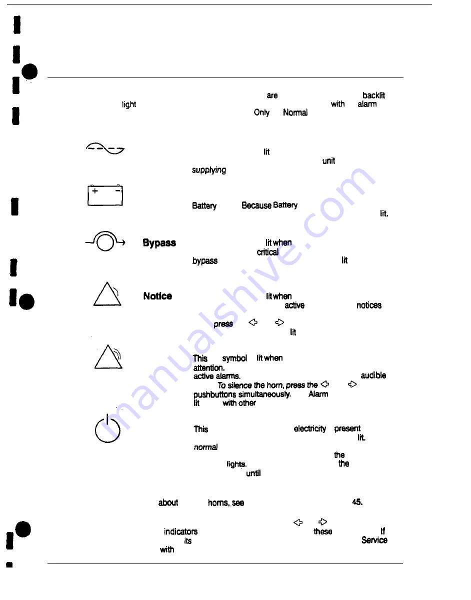
Reading the Status Indicators
The six symbols
on the left
side of the
monitor
panel
status indicators. They are
by colored
emitting diode (LED) lamps, and they work in conjunction
the
horn let you know the operating status of the UPS.
the
indicator is visible
during normal UPS operation:
Normal
Battery
Alarm
Standby
This green symbol is when the UPS is operating in
Normal mode. The power processing
(PPU) is
power to the critical load.
This yellow symbol is lit when
me
UPS is operating in
mode.
mode is a normal
condition of the UPS, the Normal indicator also remains
This yellow symbol is
me
UPS is operating in
Bypass mode. The
load is
supported
by the
source. The Normal indicator is not when the
system is in Bypass mode.
This yellow symbol is
me
system needs attention.
The LCD screen shows all
notices. Some
may be accompanied by an audible horn. To silence the
horn.
the
and
pushbuttons simultaneously.
The Notice indicator may be along with other indicators
red
is
a situation requires immediate
The LCD screen shows the highest priority
All alarms are accompanied by an
horn.
and
The
indicator may be
along
indicators.
yellow symbol is Iii when
is
in me
PPU of the UPS end the Normal indicator is not
During
startup, this indicator lights until the the UPS
transfers to Normal mode, at which point
Normal
indicator
During normal shutdown,
Standby
indicator lights
all energy in the UPS is dissipated and
shutdown is complete.
For
more
information
audible
System Event Horns’ on page
To test the LED lamps behind the status indicators, press the
and
pushbuttons
simultaneously. All
me
should light while you hold down
pushbuttons.
any indicator does not light,
LED
may need
to be replaced. Contact Customer
if you have a problem
the indicator lamps.
22
Power-ware Plus 80 UPS Operator’s Manual
Содержание Plus 80
Страница 1: ...0 Powerware Plus 80 Unintemqtibk Power Supply Operation 164200252 Rev A...
Страница 55: ...a 1 a Pe WNP U N I N T E R R U P T I B L E P O W E R S Y S T E M S I i b I EXlDE ELECTRONICS...
Страница 72: ...I I I I I I U N I N T E 4 f RRUPTIB Z a L E P O W E R SYSTEMS P 10 I I I I I I I L INS I HIDE fLECTRONICS...
Страница 88: ...I I I I I I IO I I I I b I I NOTES 10 Powemam Plus 60 UPS ln stallation Manual...
Страница 146: ...1111111111111111 llllllllllllllll 1111111111111111 llllllllllllllll A 12 Pawemare Plus 80 UPS hstallation Manual...
Страница 147: ...2 I FRONT Powerware Plus 80 UPS installation Manual A 13...
Страница 153: ...5 61 CRE47Eo By L ORLANDO RMWON A ONE B 269r Powemare Plus 90 UPS lnstailation Manual A 19...
Страница 157: ...19 0 FLUSH MOUNT 750 I A t 00 00 iI I F 190 5 7 50 Relay Interface Module DEScX p RELAY INTERFACE MODULE 33 _...


